Snap hook with interlocking gate

Active Publication Date: 2011-09-13
RELIANCE INDUSTRIES LIMITED
View PDF43 Cites 36 Cited by
  • Summary
  • Abstract
  • Description
  • Claims
  • Application Information

AI Technical Summary

Benefits of technology

[0014]Another important inventive feature disclosed here is the cooperation, and structure for achieving the cooperation, between the nose of the J-shaped body and the gate. It has been discovered that the cooperation of the nose and the gate greatly influences the strength, or load carrying capacity, of the disclosed snap hook. According to a highly preferred embodiment of the invention, the tip of the gate includes an aperture or recess and the nose of the hook includes a male portion that extends into the aperture or recess when the gate is in the clo

Problems solved by technology

Because of the variety of attachment points and work condition present during an instance where the safety hook and fall arrest systems must be deployed, the actual fall path and restrain conditions are rather unpredictable.
The use of the snap is connected or snapped back around the lanyard itself has several inherent problems.
The first problem is that the lanyard webbing can lie across the inside of the snap gate.
A danger with the use of snap hooks is that a snap, when looped over an I-beam with the edge of the gate against the flange of the I-beam, can fail by forces on the gate which can open by the due to the action of the I-beam pressing against the gate during fall arrest.
This situation is particularly problematic for a snap hook, since the cooperation of the ga

Method used


Image

  • Snap hook with interlocking gate
  • Snap hook with interlocking gate
  • Snap hook with interlocking gate

Examples


Embodiment Construction

[0028]While the invention will be described and disclosed here in connection with certain preferred embodiments, the description is not intended to limit the invention to the specific embodiments shown and described here, but rather the invention is intended to cover all alternative embodiments and modifications that fall within the spirit and scope of the invention as defined by the claims included herein as well as any equivalents of the disclosed and claimed invention.

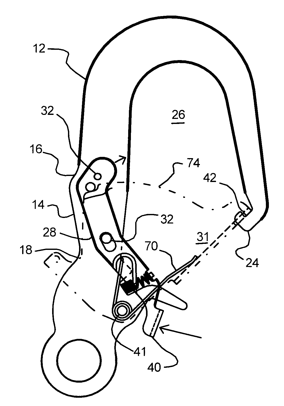
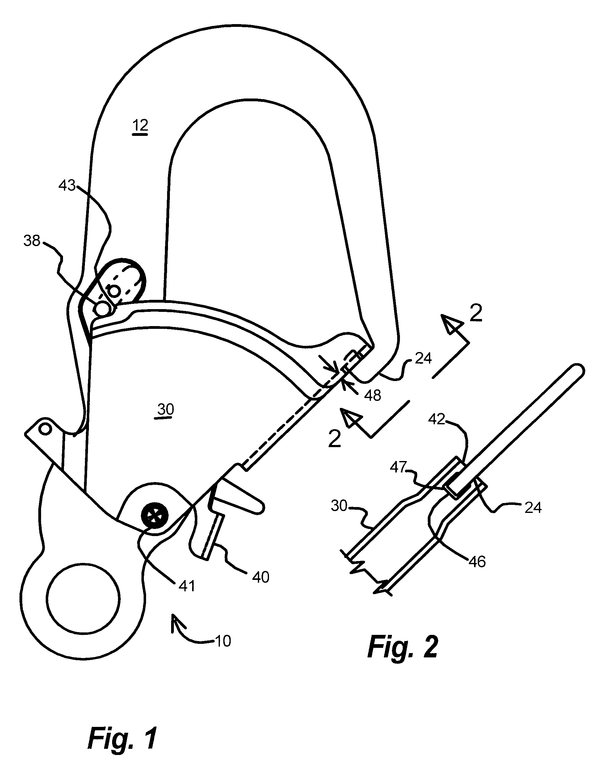
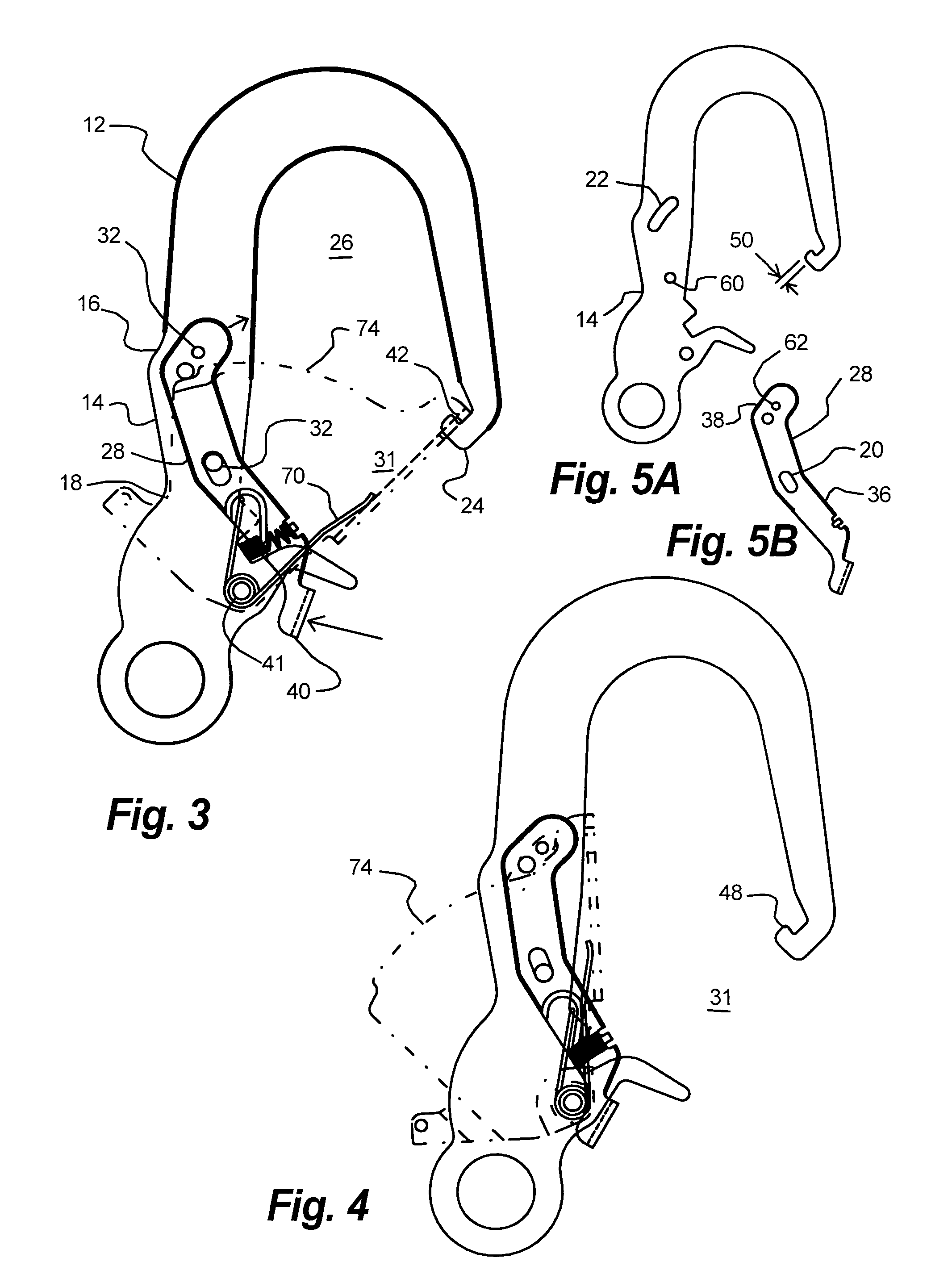
[0029]Turning now to FIGS. 1 and 5A it will be understood that the disclosed snap hook 10 includes a J-shaped body 12 that has a shank portion 14 with a first end 16 and a second end 18. The shank portion 14 includes a first end 16 and a second end 18. As shown in FIG. 5A, the body 12 includes a first slot 20 at the second end 18 of the shank portion 14. These figures also illustrate that the J-shaped body 12 includes a nose 24 and a concave portion 26. The concave portion 26 extends from the second end 18 of the sh...


PUM


Abstract

A snap hook that includes gate that includes and aperture that accepts a male portion that protrudes from the nose portion of the hook is disclosed. The coupling of the nose portion and the gate prevents the unwanted opening of the gate while the hook is under extreme loads. Still further, the use of a slide bar that is moved through translation and rotation when opening the gate of the hook is also disclosed. The translation and rotation motion provides improved cooperation of the components and improves the resistance of undesired movement of the slide bar by forces against a protrusion on the slide bar, and thus provides greater resistance to unwanted opening of the gate.

Description

REFERENCE TO RELATED APPLICATIONS[0001]This application is discloses a hook with a locking gate. A hook with a locking gate is also disclosed in my co-pending application having Ser. No. 11 / 713,766, filed Mar. 2, 2007, titled Tie-back snap hook.BACKGROUND OF THE INVENTION[0002](a) Field of the Invention[0003]This application relates to snap-hook that includes a locking mechanism for keeping the gate of the snap-hook in a closed or locked position. The snap-hook is designed for use with a lanyard in personal fall protection.[0004](b) Discussion of Known Art[0005]Snap-hooks are extremely popular in the field of fall protection. These hooks are typically attached to a lanyard that is used between a worker and a support structure or feature. One end of the lanyard is attached by way of a safety hook to the back of a harness, while the other end of the lanyard is attached to some sort of support structure, such as a crane, a section of steel or rebar, or other attachment point specifical...

Claims


Application Information

Patent Timeline
IPC IPC(8): F16B45/02
CPCF16B45/02Y10T24/4534Y10T24/45372F16B45/026F16B45/027
Inventor CHOATE, GARY E.
Owner RELIANCE INDUSTRIES LIMITED
Why Eureka
Try Eureka