
Insert molding apparatus

a technology of insert molding and molding parts, which is applied in the direction of application, manufacturing tools, drawing profiling tools, etc., can solve the problems of easy deformation of insert components and hard placement of insert components, and achieve the effect of improving the quality and efficiency of insert molding

Inactive Publication Date: 2011-11-08
CHENG UEI PRECISION IND CO LTD
View PDF7 Cites 0 Cited by
  • Summary
  • Abstract
  • Description
  • Claims
  • Application Information

AI Technical Summary

Benefits of technology

The present invention provides an improved insert molding apparatus that includes a first mold and a second mold. The first mold has at least two cavity plates that cooperatively define at least one receiving groove therebetween. The apparatus also includes at least two connecting elements each having one end positioned in one of the cavity plates and the other end passing through the other cavity plate for movably connecting them. The apparatus further includes at least one elastic element that is compressibly disposed between and against the cavity plates in such a manner that the cavity plates can contact with each other or separate away from each other. The second mold is engaged with the first mold for compelling one of the cavity plates to move toward the other cavity plate so that they become in contact with each other. The apparatus uses the elastic element to adjust the distance between the cavity plates, which makes it convenient to place an insert component in the receiving groove of the first mold, improving the quality and efficiency of the insert molding.

Problems solved by technology

The distance between the two cavity plates is predetermined and cannot be adjusted, thus it is hard to place the insert components in the inserting cavities and further the insert components are easily deformed in the process of being placed in the inserting cavities.

Method used


Image

  • Insert molding apparatus
  • Insert molding apparatus
  • Insert molding apparatus

Examples


Embodiment Construction

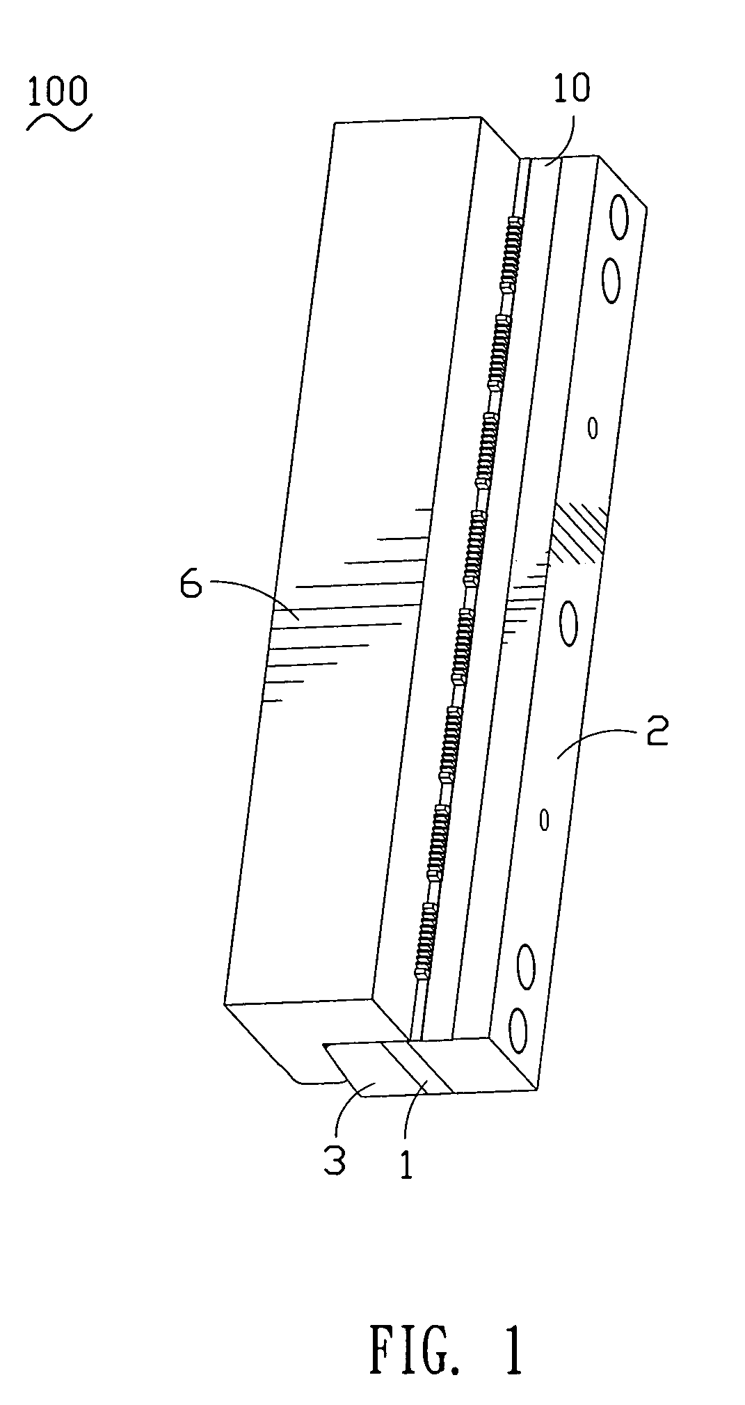
[0014]Referring to FIG. 1, an insert molding apparatus 100 according to the present invention is disclosed that includes a lower mold 10 and an upper mold 6 engaged with the lower mold 10 for fastening the lower mold 10 thereto.

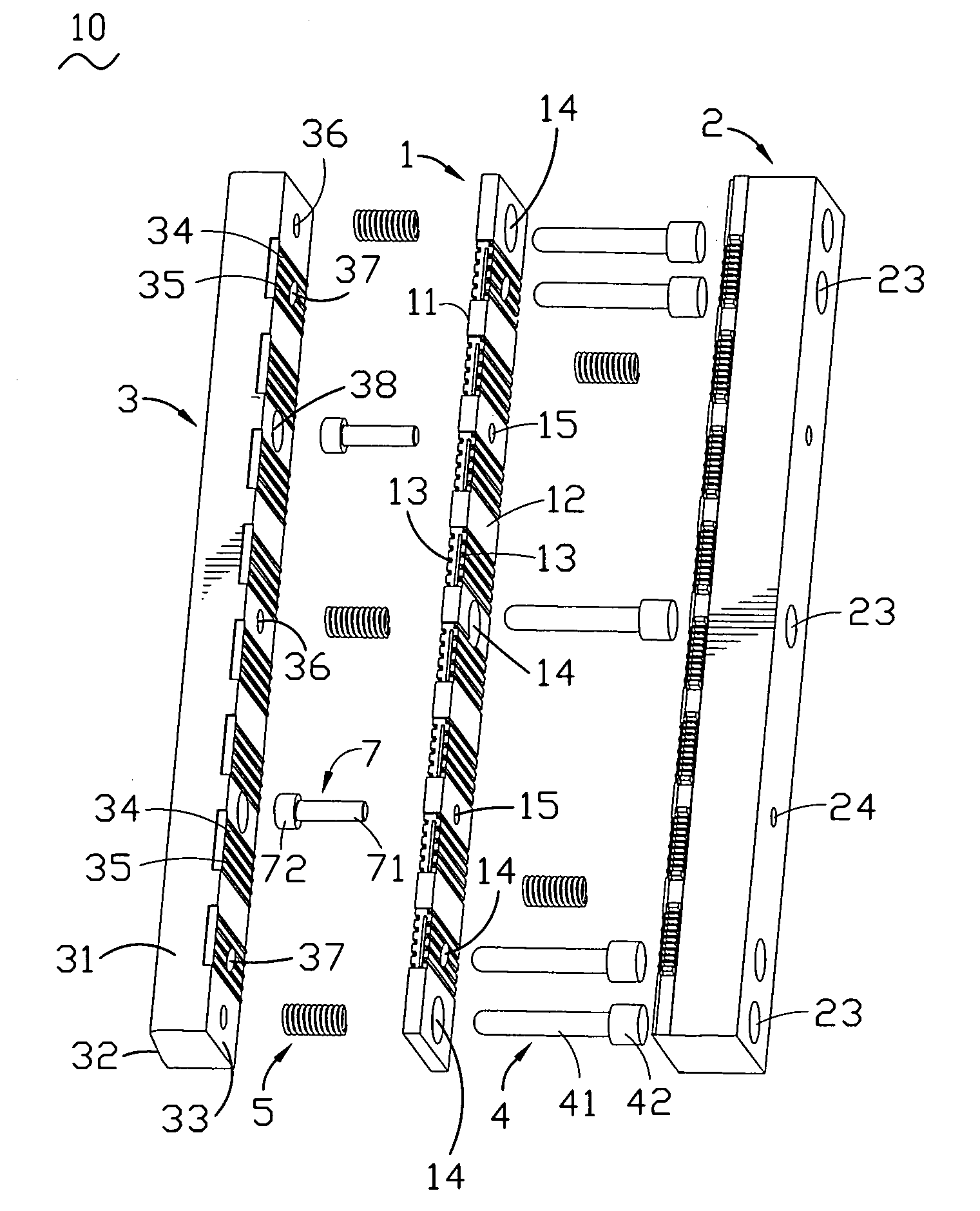
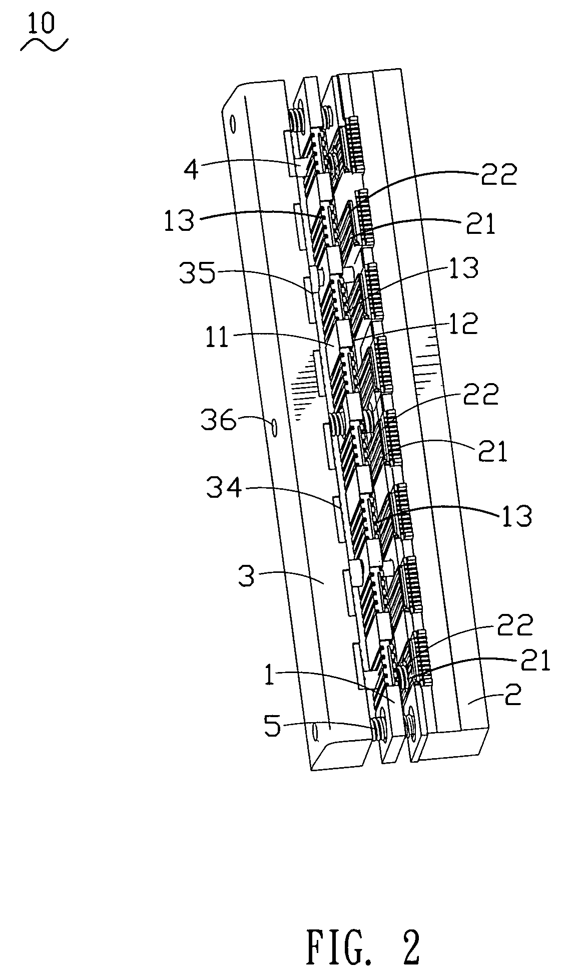
[0015]With reference to FIG. 2 and FIG. 3, the lower mold 10 includes a first cavity plate 1 including a second cavity plate 2 and a third cavity plate 3 both of which are disposed at lateral sides of the first cavity plate 1. The lower mold 10 further includes a plurality of connecting elements 4 and a plurality of elastic elements 5 cooperating with the connecting elements 4 for elastically and movably connecting the first cavity plate 1 with the second cavity plate 2 and the third cavity plate 3 together. The first cavity plate 1 is a long strip of rectangular plate and defines a first sidewall 11 and an opposed second sidewall 12. The first sidewall 11 and the second sidewall 12 each define a plurality of groups of receiving grooves 13 therein. Every two ...


PUM

PropertyMeasurementUnit
elasticaaaaaaaaaa
thicknessaaaaaaaaaa
distanceaaaaaaaaaa

Abstract

An insert molding apparatus includes a first mold and a second mold. The first mold has at least two cavity plates which cooperatively define at least one receiving groove therebetween. At least two connecting elements each have its one end positioned in one of the at least two cavity plates while the other end passing through the other cavity plate for movably connecting the at least two cavity plates with each other. At least one elastic element is compressibly disposed between and against the cavity plates in such a manner such that the at least two cavity plates are capable of contacting with each other or separating from each other. The second mold is engaged with the first mold for compelling one of the at least two cavity plates to move toward the other cavity plate so that the at least two cavity plates are in contact with each other.

Description

BACKGROUND OF THE INVENTION[0001]1. Field of the Invention[0002]The present invention relates to an insert molding apparatus, and particularly to an insert molding apparatus adapted for producing one-piece products obtained by coating insert components placed in the insert molding apparatus with resinous material and shaping the resinous material.[0003]2. The Related Art[0004]The insert molding technique is broadly used in various fields by putting insert components in an insert molding apparatus and then injecting molten resinous material in the insert molding apparatus to coat on the insert components for forming one-piece products.[0005]The insert molding apparatus conventionally includes two cavity plates which form a plurality of inserting cavities therebetween for receiving the insert components therein. The distance between the two cavity plates is predetermined and cannot be adjusted, thus it is hard to place the insert components in the inserting cavities and further the in...

Claims


Application Information

Patent Timeline
Patent Type & Authority Patents(United States)
IPC IPC(8): B22D19/04
CPCB29C45/14065
Inventor HE, PENG
Owner CHENG UEI PRECISION IND CO LTD
Learn More