Combined teething ring and pacifier and associated method

a teething ring and pacifier technology, applied in the field of pacifiers, can solve the problems of frustrated parents, infants, and reference failure to disclose the movable exterior portion of the child, and not provide a variety of unique shapes for teething units

Active Publication Date: 2011-11-15
GIBSON RHONDA
View PDF3 Cites 9 Cited by
  • Summary
  • Abstract
  • Description
  • Claims
  • Application Information

AI Technical Summary

Benefits of technology

The patent describes a device that helps infants relieve teething pain. It has a teething ring that moves back and forth to provide entertainment for the infant. The device also has an air chamber that helps the infant breathe while using the device. The thickness of the device can be adjusted to provide the necessary force to operate it. Overall, the device helps to soothe infants and reduce teething pain.

Problems solved by technology

The technical problem addressed in this patent text is the need for a combined teething ring and pacifier that is convenient, durable, lightweight, and versatile in applications. The invention aims to provide a user-friendly and enjoyable experience for infants during the teething process.

Method used


Image

  • Combined teething ring and pacifier and associated method
  • Combined teething ring and pacifier and associated method
  • Combined teething ring and pacifier and associated method

Examples


Embodiment Construction

[0041]The present invention will now be described more fully hereinafter with reference to the accompanying drawings, in which a preferred embodiment of the invention is shown. This invention may, however, be embodied in many different forms and should not be construed as limited to the embodiment set forth herein. Rather, this embodiment is provided so that this application will be thorough and complete, and will fully convey the true scope of the invention to those skilled in the art. Like numbers refer to like elements throughout the figures.

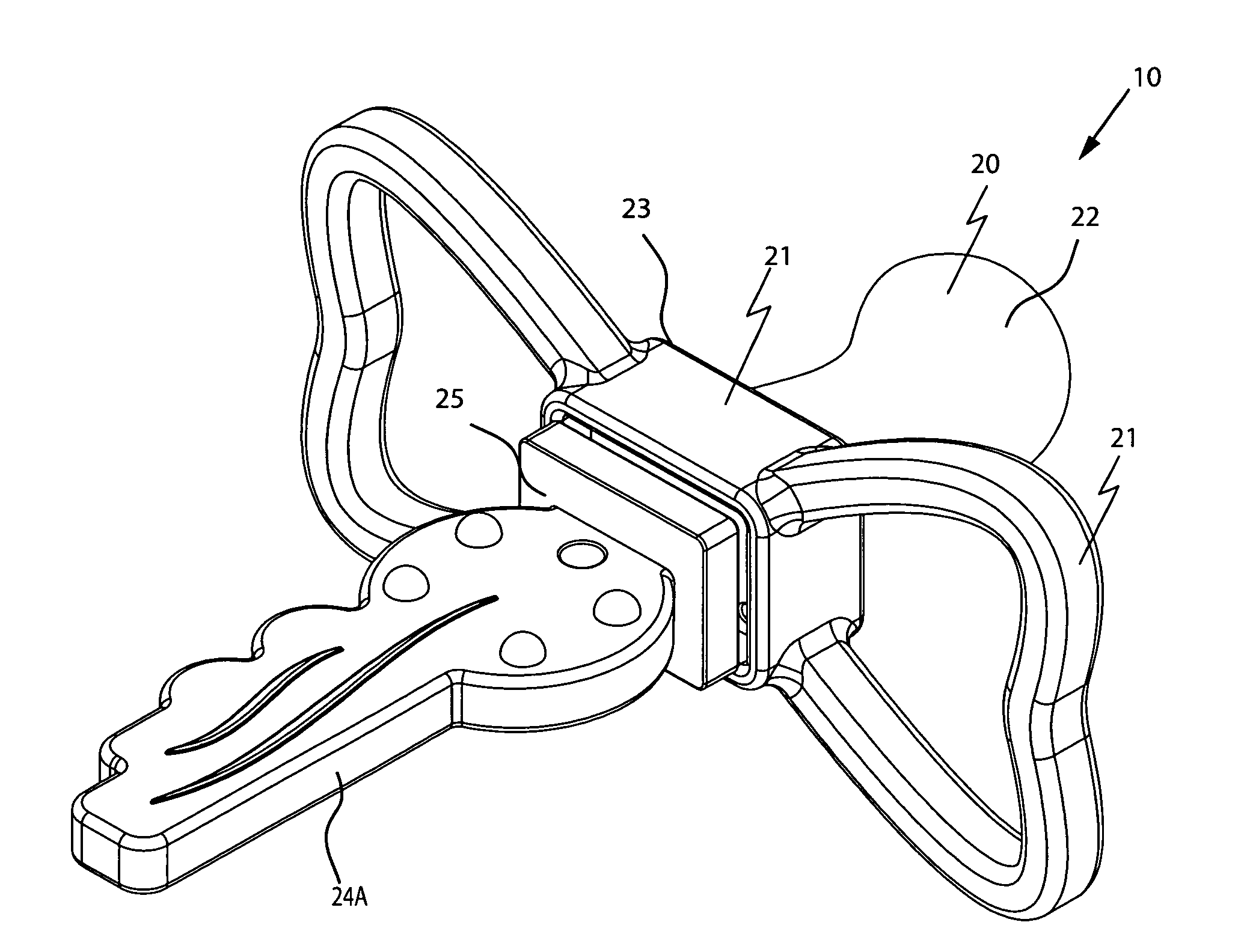
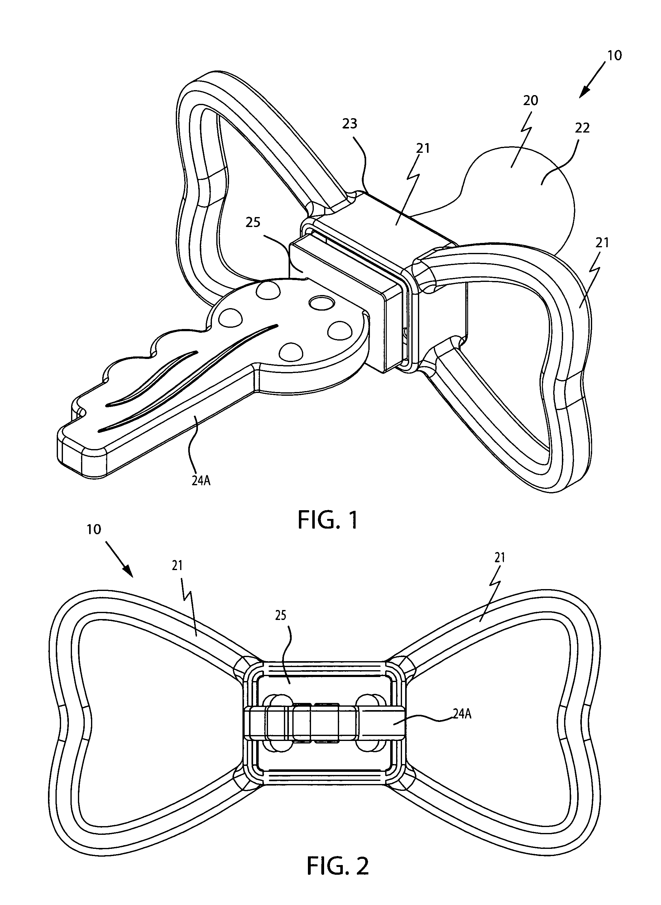
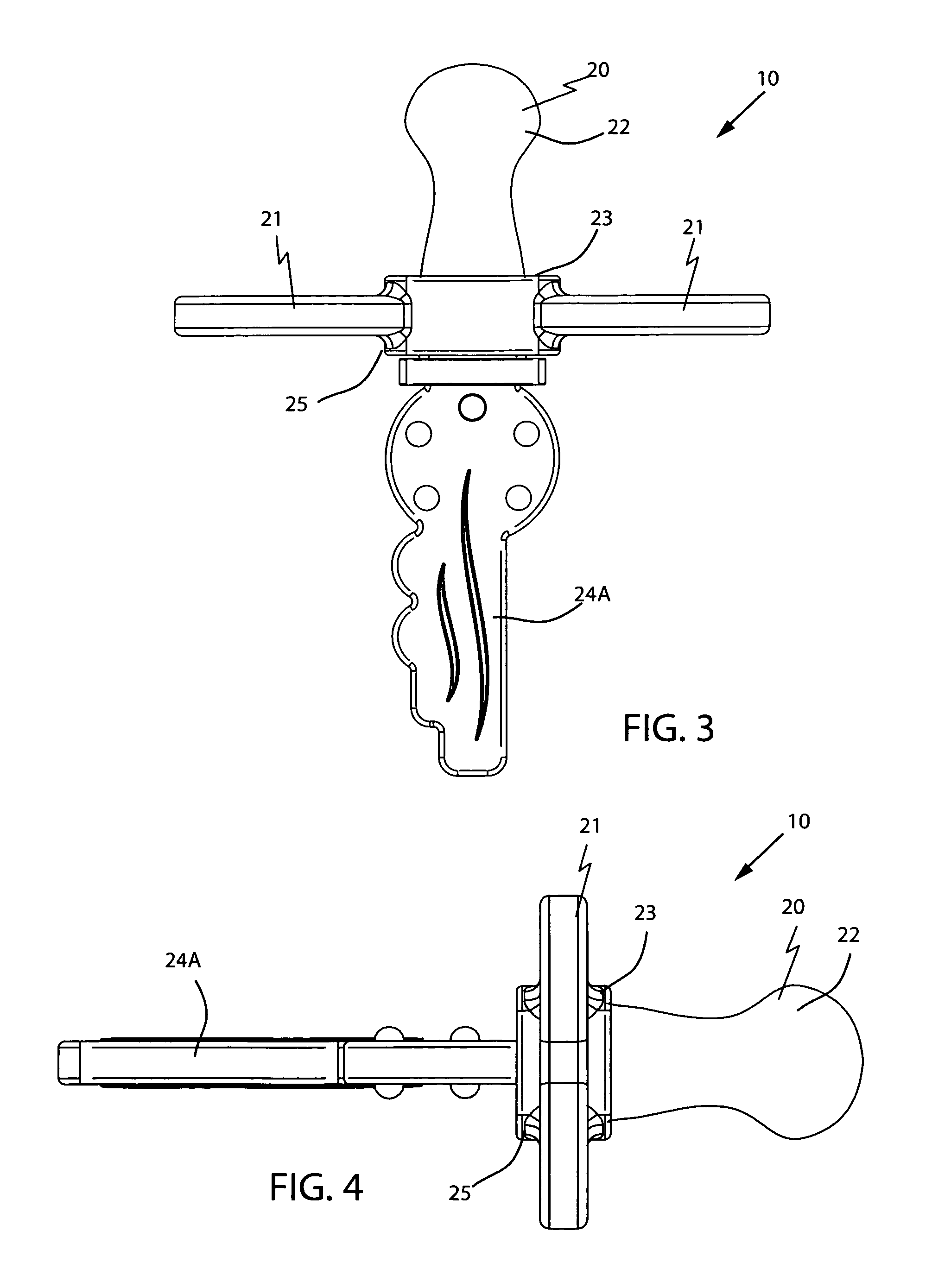
[0042]The apparatus of this invention is referred to generally in FIGS. 1-9 by the reference numeral 10 and is intended to provide a combined teething ring and pacifier. It should be understood that the apparatus 10 may be used to provide, user enjoyment many different types of infant and child needs and should not be limited in use to the applications mentioned herein.

[0043]Referring to FIGS. 1-9, a combined teething ring and pacifier 10 pre...


PUM


Abstract

A combined teething ring and pacifier may include a support member with a pacifier section and a teething ring section extending from the posterior and anterior sides thereof respectively. The teething ring may be removably coupled to the support member such that it may be removed therefrom while the pacifier remains situated inside the infant oral cavity. Multiple teething rings may be available to interchange with a single support member and pacifier. Further, the support member may include an automatic reciprocating mechanism for reciprocating the teething ring along an arcuate direction as the infant inhales air into the pacifier. The mechanism preferably includes an actuator that rotates inside an ambient-air diverting chamber as the infant breaths. With each rotation, the actuator contacts a trigger attached to the teething ring. The trigger may reciprocate along a linear path, thus urging the teething ring along the arcuate direction.

Description


Claims


Application Information

Patent Timeline
Owner GIBSON RHONDA
Why Eureka
Try Eureka