Oxidation catalyst for a combustion engine
a technology of oxidation catalyst and combustion engine, which is applied in the direction of metal/metal-oxide/metal-hydroxide catalyst, machine/engine, arsenic compound, etc., can solve the problems of increasing production errors, increasing production costs, and increasing the complexity of the method employed in preparing multi-layered oxidation catalysts, etc., to achieve good or improved performance and low co t50
- Summary
- Abstract
- Description
- Claims
- Application Information
AI Technical Summary
Benefits of technology
Problems solved by technology
Method used
Image
Examples
example 1
Preparation of a Single Layer, Non-Uniform Catalyst
[0174]Silica-alumina powder was slurried in water and milled to a d90 of less than 20 micron. A soluble platinum carboxylate salt and palladium nitrate was added to the slurry and the mixture was stirred to homogenise. The resulting washcoat was then applied to a substrate (a cordierite flow through monolith having 400 cells per square inch) using conventional coating techniques. The resulting part was dried slowly under a flow of heated air. The part was completely dry after 20 minutes of operation and was then calcined at 500° C. The fresh catalyst composition that coated the substrate was then aged by heating at 750° C. for 15 hours under hydrothermal conditions (10% water).
[0175]Slow drying conditions were used to dry the washcoat onto the substrate. These conditions were selected to allow movement of the palladium salt during drying (i.e. as the water in the washcoat evaporated) until the palladium was fixed into position by co...
example 3
Preparation and Analysis of a Multi-Layered Catalyst with a Non-Uniform Layer
[0178]A substrate monolith of 400 cells per square inch and wall thickness of 6 thousands of an inch was prepared having a two layer structure. The first layer that was coated onto the substrate (i.e. the lower layer) contained platinum and palladium on an alumina support. The weight content of platinum was greater than that of palladium. The second layer (i.e. the upper layer) had a composition was prepared using the method in Example 1 to provide a layer having a non-uniform distribution of palladium.
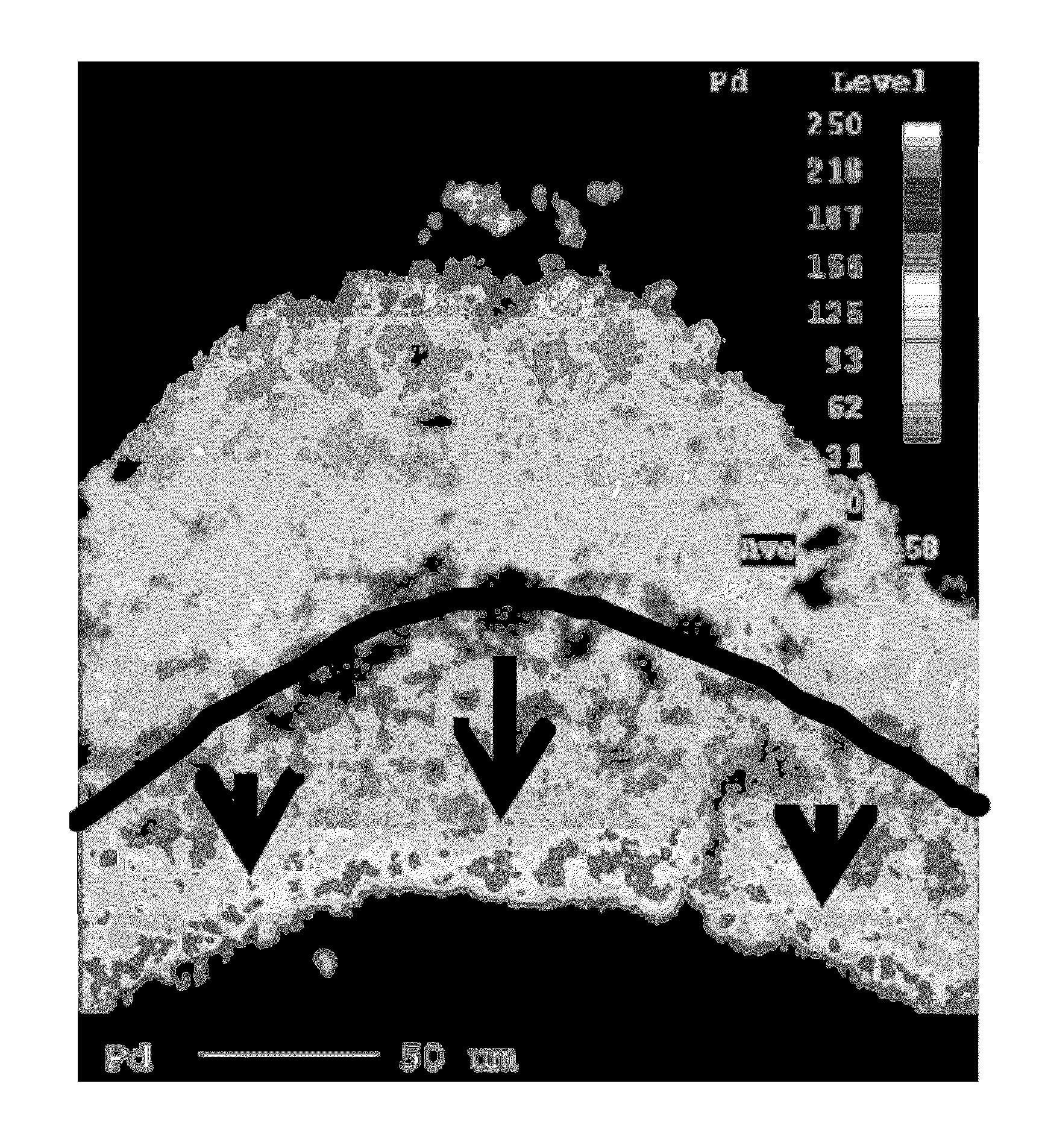
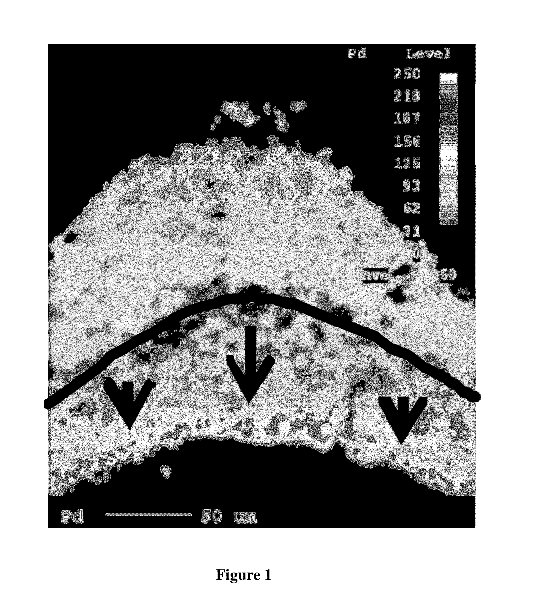
[0179]A section of the catalyst was resin mounted, ground and polished, then vacuum carbon coated. EPMA-WDX analyses showed that the first layer (i.e. bottom layer) contained a uniform distribution of palladium and platinum particles (see FIG. 1). The second layer (i.e. upper layer) contained a non-uniform distribution of palladium particles. In particular, the second layer contained a high concentration of p...
example 4
Results of Emissions Tests
[0180]Core samples were taken from each of the catalysts of Examples 1 and 2 using a 1 inch core drill. The catalyst compositions were tested in a simulated catalyst activity testing (SCAT) gas rig using the inlet gas mixture shown in Table 1 with a space velocity of 55000 / hour to mimic engine emissions.
[0181]
TABLE 1GasConcentrationCO1500 ppm HC (as C1)430 ppmNO100 ppmCO24%H2O4%O214%
[0182]The results for the aged catalysts of Examples 1 and 2 are shown in Table 2. Table 2 lists the temperatures at which 50% conversion of CO (T50 CO) and 80% conversion of HC (T80 HC) occurred.
[0183]
TABLE 2Example No.T50 CO (° C.)T80 HC (° C.)11411542147160
[0184]The results in Table 2 show that when the simulated exhaust gas is exposed to the catalyst of Example 1, which has a high concentration of palladium particles near an exposed surface of the washcoat coating, then the temperatures for 50% conversion of CO and 80% conversion of HC are lower than those obtained for Comp...
PUM
| Property | Measurement | Unit |
|---|---|---|
| D90 particle size | aaaaa | aaaaa |
| D90 particle size | aaaaa | aaaaa |
| D90 particle size | aaaaa | aaaaa |
Abstract
Description
Claims
Application Information
 - R&D
- Intellectual Property
- Life Sciences
- Materials
- Tech Scout
- Unparalleled Data Quality
- Higher Quality Content
- 60% Fewer Hallucinations
Browse by: Latest US Patents, China's latest patents, Technical Efficacy Thesaurus, Application Domain, Technology Topic, Popular Technical Reports.
© 2025 PatSnap. All rights reserved.Legal|Privacy policy|Modern Slavery Act Transparency Statement|Sitemap|About US| Contact US: help@patsnap.com


