Distributed channel allocation method and wireless mesh network therewith

a wireless mesh network and channel allocation technology, applied in wireless communication services, wireless commuication services, electrical appliances, etc., can solve the problems of inability to avoid interference in the above-mentioned techniques, limited application of the method, and reduced data transmission rate of the network link layer, so as to achieve the effect of avoiding interference among nodes and ensuring the application of bandwidth

Inactive Publication Date: 2011-11-15
IND TECH RES INST
View PDF8 Cites 166 Cited by
  • Summary
  • Abstract
  • Description
  • Claims
  • Application Information

AI Technical Summary

Benefits of technology

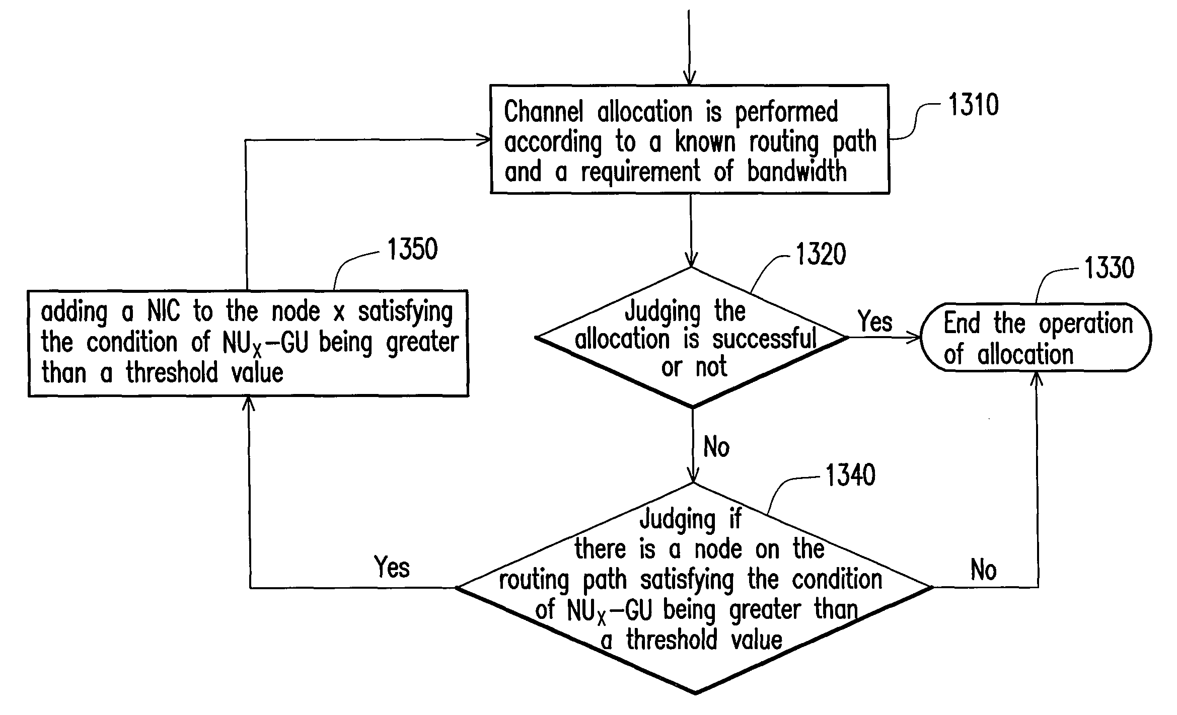
[0014]The present invention is directed to a channel allocation method for a mesh network having a multi-wireless network interface, by which the interference among nodes can be avoided, and an applicable bandwidth can be guaranteed.
[0016]The present invention is directed to a distributed channel allocation method for a mesh network having a wireless network interface. By the distributed channel allocation method, the interference is avoided in the wireless network communication, such that an allocated bandwidth can be fully utilized, and unnecessary depletion of the allocated bandwidth due to the interference can be avoided.
[0017]The present invention is directed to a distributed channel allocation method for a mesh network having a wireless network interface. By this method, a time division technique is applied for dividing a transmission time of each wireless NIC, and different non-overlapping channels can be assigned in different timeslots, which is different from other studies that require a symmetrical number of the NICs between a receiving node and a transmitting node. Moreover, in this method, a unique wireless NIC may communicate with a plurality of the wireless NICs. The method provides the feature that the number of the NICs on a certain node can be adjusted to meet a communication requirement, and efficiency of a network flow is also significantly improved.

Problems solved by technology

Furthermore, the most serious issue lies in that a data transmission rate of a network link layer may be decreased greatly due to signal interference.
However, this channel allocation method only takes the optimal channel within one hop between the AP and the MN into account.
Therefore, the application of the method is limited.
However, the interference still cannot be avoided in the aforementioned techniques.

Method used


Image

  • Distributed channel allocation method and wireless mesh network therewith
  • Distributed channel allocation method and wireless mesh network therewith
  • Distributed channel allocation method and wireless mesh network therewith

Examples


first embodiment

Basic Channel Allocation Method

[0072]First, a network structure with a single timeslot, four channels, and four NICs is taken for an example to explain the channel allocation method. Since there is only a single timeslot, an individual NIC can merely communicate with another NIC synchronously. Therefore, in this example, the number of the NICs on each node is assumed to be equal to the number of the non-overlapping channels.

[0073]First, a three-tuple (a1, a2, a3) is defined as a combination of correlative free channels, wherein a3 is the free channel of the present link, a2 is the free channel of the previous link, and a1 is the free channel of the previous two links. FIG. 6 is a calculated result of FIG. 5. FC(u,v) represents the free channel from a node u to a node v, whereas FCSPn represents a path selected by the three-tuple in the present embodiment.

[0074]The following formulas denote the definition of the free channel combination FCSPn:

FCSPn≡{(c1,c2,c3)|c1εFCPn-2, c2εFCPn-1, c...

second embodiment

The Second Embodiment

Sharing The Allocated Transmission Path by Distribution in Priority

[0079]To expanding the method of the first embodiment, a further embodiment is provided, wherein the allocated transmission paths can be shared according to the channel allocation method of the present invention, and the utilization efficiency of the network can be greatly improved. FIG. 8 represents a modified FIG. 4. Besides, it is assumed that the allocated channels already exist between nodes n1 and n2, nodes n2 and n3, nodes n3 and n4, and that the channels are transmitting packets, shown as arrows of reference numerals 810, 820 and 830. Referring to FIG. 8, a first channel is already allocated between the nodes n1 and n2, a third channel is already allocated between the nodes n2 and n3, and a fourth channel is already allocated between the nodes n3 and n4. If the remaining bandwidth of the allocated channels is greater than the bandwidth required for the routing path to be established, the ...

third embodiment

The Third Embodiment

Channel Allocation Method of Multi-Timeslots, Multi-Channels And Unique NIC

[0082]Another feature of the present invention will be described in the present embodiment. A time division technique is introduced to the previous channel allocation method, by which the number of the NICs on the receiving node and the transmitting node are allowed to be asymmetric. A situation of three timeslots, four non-overlapping channels and one NIC for each node is taken for an example to describe the channel allocation method of the present invention.

[0083]Referring to FIG. 10, it should be noted that the channel utilization is categorized into four states: transmitting (T), receiving (R), interfered (I) and free (F). In FIG. 11, the “T” state is shown by left-slanted lines, which represents the channel is transmitting packets. The “R” state is shown by right-slanted lines, which represents the channel is receiving the packets. The “I” state is shown by cross lines, which represen...


PUM


Abstract

A distributed channel allocation method and a wireless mesh network with the same are provided herein. By the distributed channel allocation, interference situations are avoided in a wireless network communication, and the allocated bandwidth can then be fully utilized. Besides, unnecessary depletion of an allocated bandwidth due to the interference can be avoided. By this method, a time division technique is applied for dividing a transmission time of each wireless NIC, and different non-overlapping channels can be assigned to different timeslots. Different from other researches that require a symmetrical number of the NICs between a receiving node and a transmitting node, in this method, a unique wireless NIC may communicate with the wireless NICs. The method provides the feature that the number of the NICs on a certain node can be adjusted to meet a communication requirement, by which the efficiency of a network flow is also significantly improved.

Description

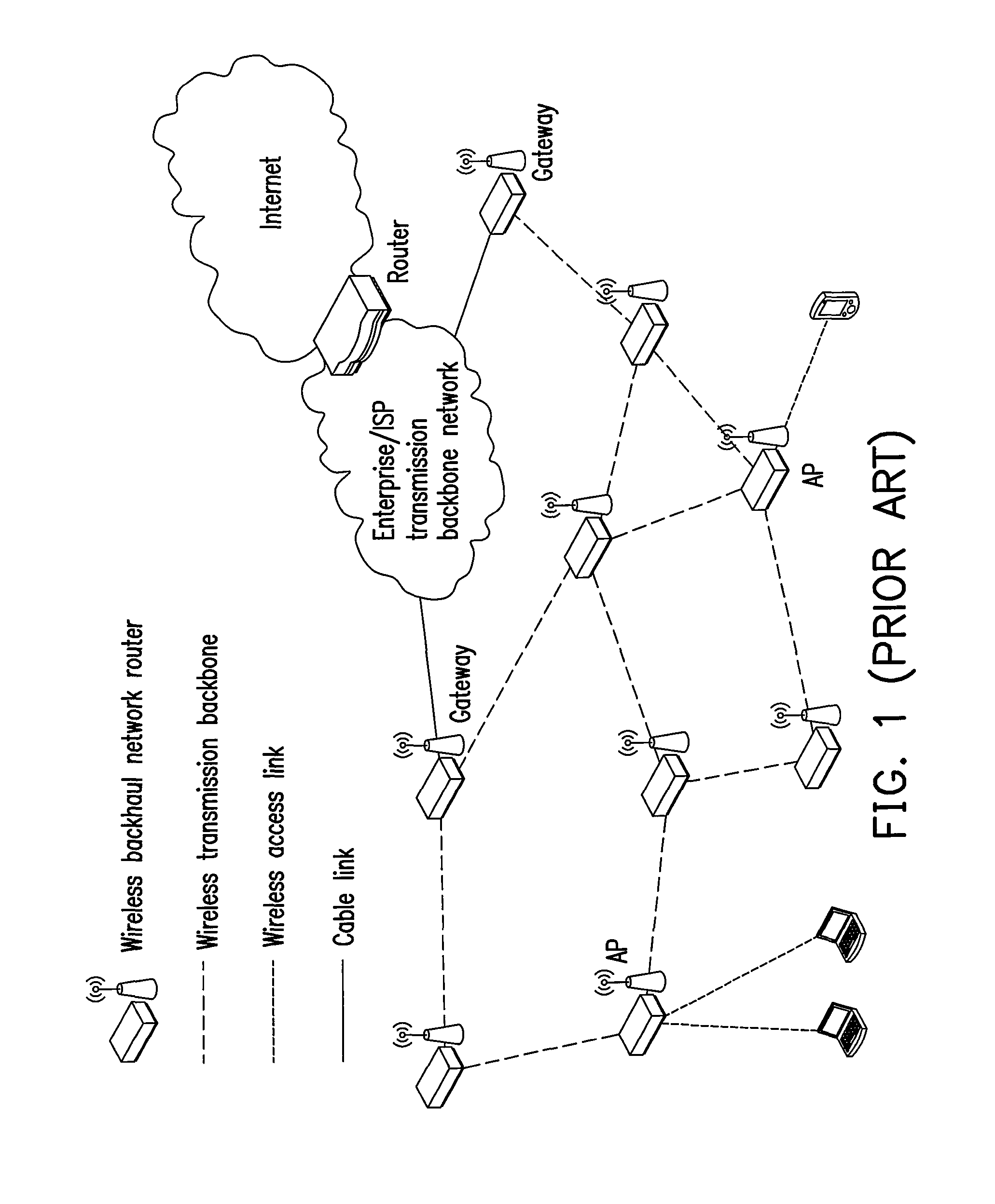
CROSS-REFERENCE TO RELATED APPLICATION[0001]This application claims the priority benefit of Taiwan application serial no. 96111609, filed Apr. 2, 2007. All disclosure of the Taiwan application is incorporated herein by reference.BACKGROUND OF THE INVENTION[0002]1. Field of the Invention[0003]The present invention relates to a channel allocation method of a wireless network and a system thereof. More particularly, the present invention relates to a distributed channel allocation method of a wireless mesh network and a system thereof.[0004]2. Description of Related Art[0005]In recent years, there is a rapid development in the field of wireless broadband access techniques including Wi-Fi (IEEE 802.11 series), WiMAX (IEEE 802.16 series) and 3G, etc. The wireless mesh network (referred to hereinafter as WMN, IEEE 802.11s) is one of the key techniques integrated with the wireless broadband network. The structure of the WMN illustrated in FIG. 1 is a mesh network based on a wireless transm...

Claims


Application Information

Patent Timeline
Patent Type & Authority Patents(United States)
IPC IPC(8): H04W4/00H04W72/00
CPCH04W40/16H04L45/12
Inventor SHIH, YUNG-CHIENYANG, JEN-SHUNTSENG, CHIEN-CHAO
Owner IND TECH RES INST
Why Eureka
Try Eureka