Method and system for automatically performing a study of a multidimensional space

a multi-dimensional space and automatic study technology, applied in the field of automatic study of multi-dimensional space, can solve the problems of costly corrective action, costly redesign of design drawings, and difficulty in achieving a design from concept to implementation

Inactive Publication Date: 2011-11-15
STATHIS SAM
View PDF38 Cites 34 Cited by
  • Summary
  • Abstract
  • Description
  • Claims
  • Application Information

AI Technical Summary

Benefits of technology

[0009]The automatic layout of the multidimensional space a construction site in accordance with the method and system of the present invention involves using points of references such as benchmarks and targets to establish the location, position and orientation of one or more structures and / or objects designated to be disposed within the multidimensional space. Typically a design for the development of a multi-dimensional space is memorialized as one or more drawings (e.g., CAD or Computer Aided Design drawings) that precisely depict the spatial relationships between objects and / or structures of the multi-dimensional space to be constructed. The design, when depicted graphically, represents a virtual space having specific physical features. During the execution of the automatic layout of the multi-dimensional space by a user of the system of the present invention, the system, with reference to the design drawings, orients itself within the multi-dimensional space and then points out the precise location of selected objects and / or structures contained in the design drawings as they would translate to the multi-dimensional space. Thus, the present invention is able to guide the user within the multi-dimensional space to a single point (or area or volume or other higher dimensional region) enabling the user to make markings within the multi-dimensional space indicating the specific positioning, orientation and / or arrangement of objects and / or structures to be constructed at or within the boundaries of the multi-dimensional space. In one embodiment of the present invention, the user is able to control equipment of the system of the present invention to automatically make the markings for structures and / or objects specified in the design.
[0010]The system of the present invention comprises components including at least one Master station, a Processor, and one or more targets. The components of the system of the present invention are in communication with each other to allow the system to perform an automatic study and layout of a multidimensional space. During the study and / or layout of the multidimensional space, the system can guide a user within the multi-dimensional space by displaying the multi-dimensional space (e.g., a 3D graphics representation), including known or already studied objects and / or structures and the user's current physical location simultaneously effectively guiding the user within the multi-dimensional space and effectively indicating to the user where to make markings when the user is performing a layout of the multidimensional space. Further, the system of the present invention can display the virtual space as an overlay to the multi-dimensional space depiction. Thus, as the user physically moves within the multi-dimensional space, the system of the present invention is able to track the user's location and display said location within the graphical representation of the actual and / or virtual space in real time. The display can be part of the Master Station or part of the Processor or both components can have displays.

Problems solved by technology

Realization of a design from concept to implementation is a challenge, particularly as it relates to the construction industry.
Errors by contractors in replicating what the design documents indicate are a common feature of construction practice and one that oftentimes results in costly corrective action.
In some instances, the error is due to the lack of a real appreciation of the characteristics of a site at which construction is to take place.
For example, if the design for a space to be renovated calls for a door to be placed in a specific location and that location at the construction site turns out to have a column in the exact location where the door is called for, a costly redesign of the design drawings may become necessary.
Another common occurrence that leads to costly remedial measures is where inaccurate layout of a construction site leads to construction of major elements of the design in the wrong place leading to costly retrofitting when the error is ultimately discovered.
When errors occur in the performance of these tasks, the type of errors described above result.
Sometimes errors are not due to inaccurate measurements or ‘as built studies’, but rather to poor control of monuments such as when a monument or benchmark such as a stake is inadvertently knocked over or a pencil mark is inadvertently smeared in the field by a person or a piece of equipment.
When this occurs, any subsequent reference to this benchmark will result in errors resulting from the fact that a dimensional control is now in the wrong place but not known to be in the wrong place.
Moreover, errors resulting from the use of the now inaccurate reference point can be further compounded by the fact that the errors may not be discovered for some time.
In practice, this task can be extremely time consuming and labor intensive typically requiring crews of personnel to revisit a site frequently and manually verify existing benchmarks and monuments or as needed, manually establish new benchmarks and monuments.

Method used


Image

  • Method and system for automatically performing a study of a multidimensional space
  • Method and system for automatically performing a study of a multidimensional space
  • Method and system for automatically performing a study of a multidimensional space

Examples


first embodiment

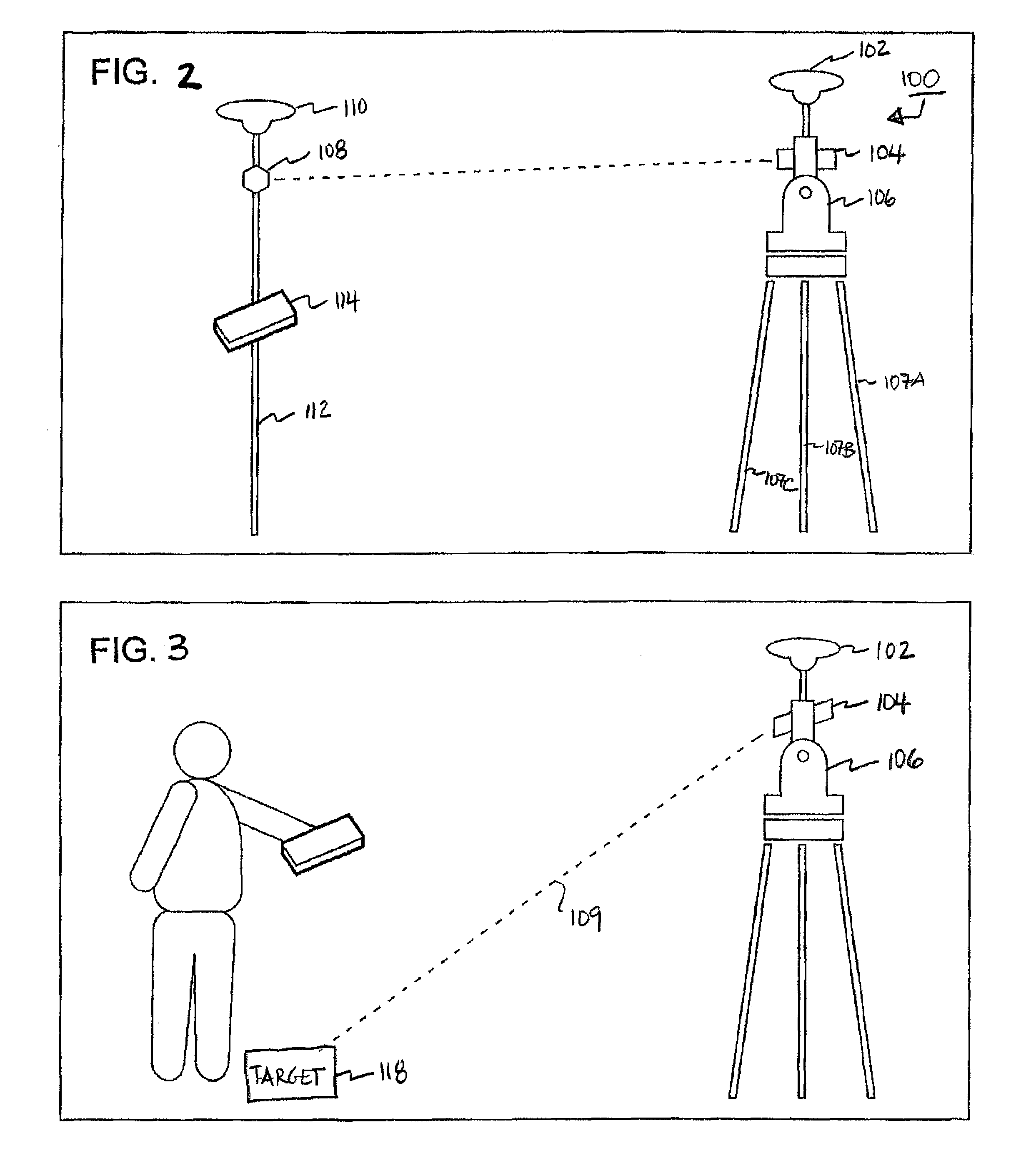
[0045]Referring temporarily to FIG. 2, there is shown the system of the present invention comprising Master station module 100 (shown as a stationary robotic device) having a tripod (107), laser range finder 104, a wireless communications device 102 (including an antenna) located on top, and a computer and user interface 106. The system further comprises Processor 114 and at least one target such as prism 108. Master station module, implemented as a total station is a robotic device that moves laser 104 to constantly track prism 108 located on pole 112 which is similar to a surveyor's pole, except that it too has a wireless communications device 110 located at one of its ends as shown. The total station knows the location of the prism, and that location is communicated to Processor 114 through communication device 110 by Master station module 100. Communication device 100 is coupled to Processor 114 and is used by Processor 114 to receive and / or transmit information to Master statio...

second embodiment

[0051]FIG. 3 shows the system of the present invention wherein the Master station module 100 (e.g., Leica total station 1200 series model 3) points its laser beam 109 at a target 118, the location of which is determined by a user 116 inputting coordinates into the Processor 114, and the coordinates are communicated wirelessly to the total station. The user tells the Processor 114 the position where it wants the laser to illuminate, and the Master station module's laser beam is directed to that position.

third embodiment

[0052]FIG. 4 shows a third embodiment wherein the Master station module 100 locates prism 108 physically located on mobile robot 122 having a substation 120 mounted thereon. The Master station module 100 station comprises software which can direct the mobile robot to a specific location via wireless communications. The mobile is “blind,” but it is navigated by the Master station module 100 circuitry under the control of the software residing in the computer 106 of the master station module 100. The substation 120 mounted onto the mobile unit 122 can perform similar operations to that of Master station module 100, but is under the control of module 100. The mobile robot also comprises a wireless communications device 110 and a laser 118. The mobile robot's laser can then illuminate any point location requested by the Master station module 100. This is useful since Master station module 100 is stationary, and some locations are not available to the Master station module by line-of-sig...


PUM


Abstract

A method and system comprising a Master station, a processor and one or more targets that allows a user of said system to automatically generate a 3 dimensional graphical representation of a construction site and also overlay a drawing onto the graphical representation to guide the user within a virtual space being displayed by the processor.

Description

[0001]This application claims the benefit of the filing date of a provisional application having Application No. 60 / 805,983 titled “Method for Accurately and Precisely Locating and Marking a Position in Space Using Wireless Communications” filed on Jun. 28, 2006.FIELD OF THE INVENTION[0002]The present invention relates to a system and method for generating, in automatic fashion, a graphical representation of a multidimensional space.BACKGROUND OF THE INVENTION[0003]Realization of a design from concept to implementation is a challenge, particularly as it relates to the construction industry. In the construction industry, architects, planners, engineers and the like are charged with the task of conceptualizing ideas and reducing the concepts to tangible form such as design drawings, that can then be implemented by contractors in the field. The implementation or construction process can be an arduous task, the success of which relies heavily on the ability of a contractor to accurately...

Claims


Application Information

Patent Timeline
Patent Type & Authority Patents(United States)
IPC IPC(8): G06F17/50G05D1/02G01C9/00G01C3/00G01C3/08G01B11/26G06F7/60G06F3/048G06G7/48
CPCG01C15/002G06F17/40
Inventor STATHIS, SAM
Owner STATHIS SAM
Why Eureka
Try Eureka