
Electronic fluidic indicator and method of indicating

Inactive Publication Date: 2013-01-03
TEKNOLOGIAN TUTKIMUSKESKUS VTT OY
View PDF5 Cites 6 Cited by
  • Summary
  • Abstract
  • Description
  • Claims
  • Application Information

AI Technical Summary

Benefits of technology

This patent describes a new way to detect exposure to environmental factors that can damage or change the status of an object. The invention provides a reliable and cost-effective solution that can respond to a variety of things like physical, chemical, or other environmental factors. The invention can also trigger a power supply to power electronic circuits that can indicate the presence of a harmful stimulus. The invention can be used for brand promotional purposes and is suitable for mass production and use in consumer packages.

Problems solved by technology

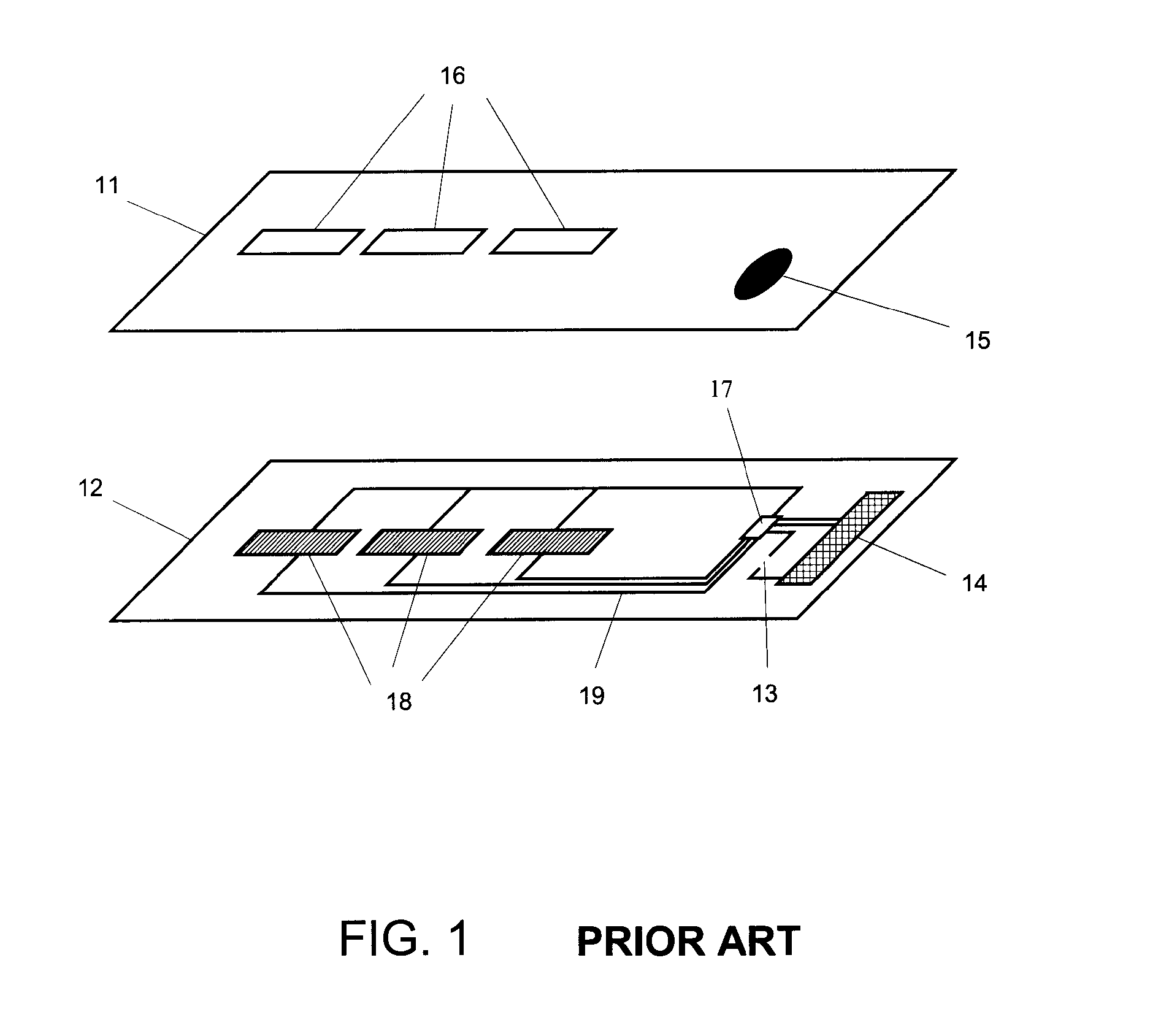
Above the critical temperature (freezing the solutions) the structure that immobilises the solutions is damaged and exposure to a given temperature during suitable time (melting the solutions), the solutions are no longer immobilised and they can intermingle causing a reaction which is visible.
However, such electronic devices prove to be expensive to be used systematically on all the product items for which it is wished to monitor the temperature.
There is also a disadvantage that the electronic circuits such as the sensor probe, microcontroller and transmitter have to be powered by a battery which is expensive and difficult to implement on a disposable product label.
However, this kind of electronic indicator has to be manually activated and it only relies on counted time and therefore it does respond to actual exposure to harmful stimulus of physical, chemical or other environmental phenomena.
Further, it requires the battery which is expensive and difficult to implement on a disposable product label.

Method used


Image

  • Electronic fluidic indicator and method of indicating
  • Electronic fluidic indicator and method of indicating
  • Electronic fluidic indicator and method of indicating

Examples


Embodiment Construction

[0030]The embodiments of the invention presented in this document are not to be interpreted to pose limitations to the applicability of the appended claims. The verb “comprise” or any other variation thereof is used in this document as an open limitation that does not exclude the existence of also unrecited features. The features recited in depending claims are mutually freely combinable unless otherwise explicitly stated. The terms “a”, “an” and “at least one”, as used herein, are defined as one or more than one. The term “plurality”, as used herein, is defined as two or more than two. The terms “including” and “having”, as used herein, are defined as comprising. The term “another”, as used herein, is defined as at least a second or more. The term “or” is generally employed in its sense including “and / or” unless the content clearly dictates otherwise. For the above-mentioned defined terms, these definitions shall be applied, unless a different definition is given in the claims or e...


PUM


Abstract

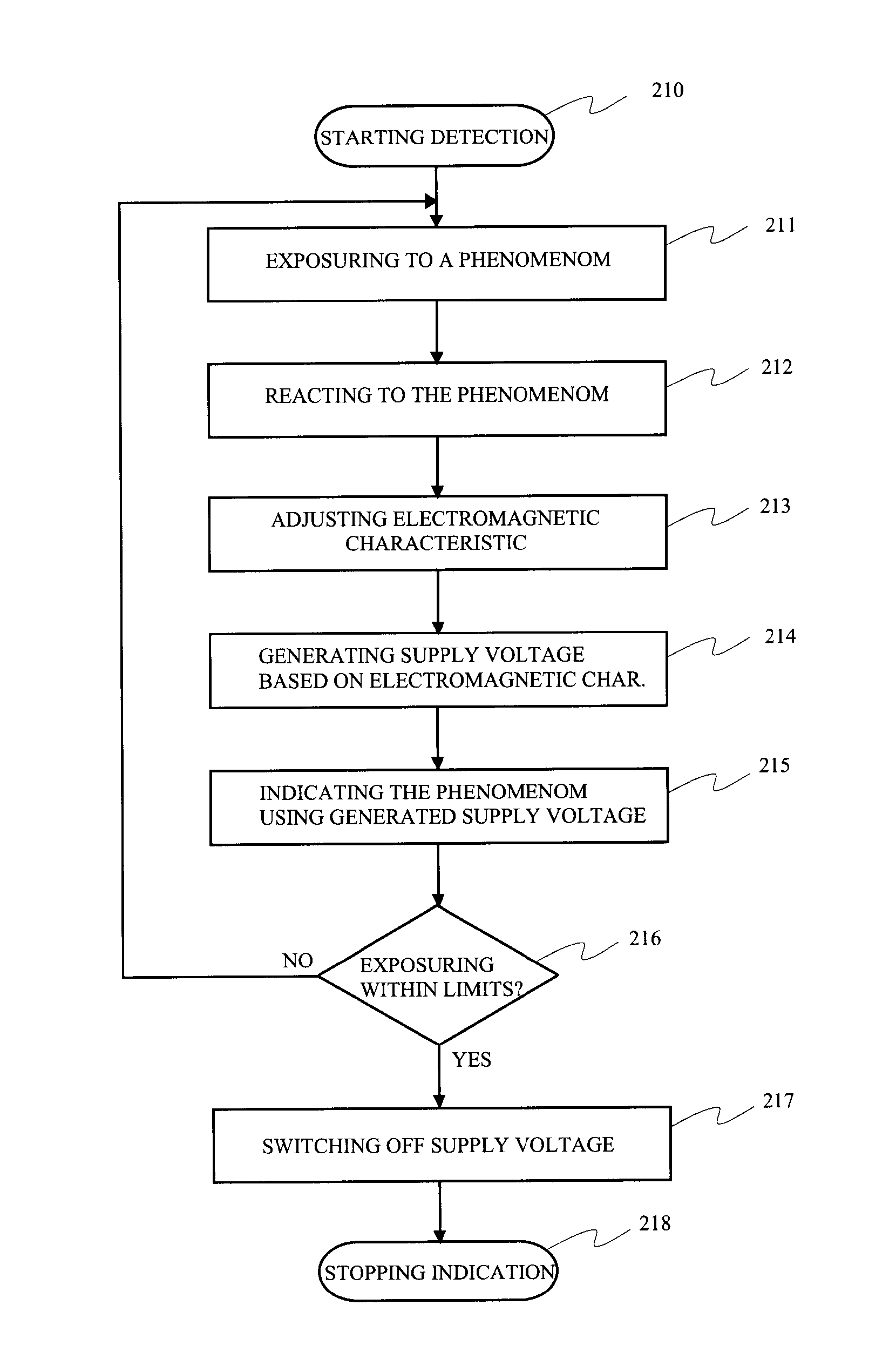
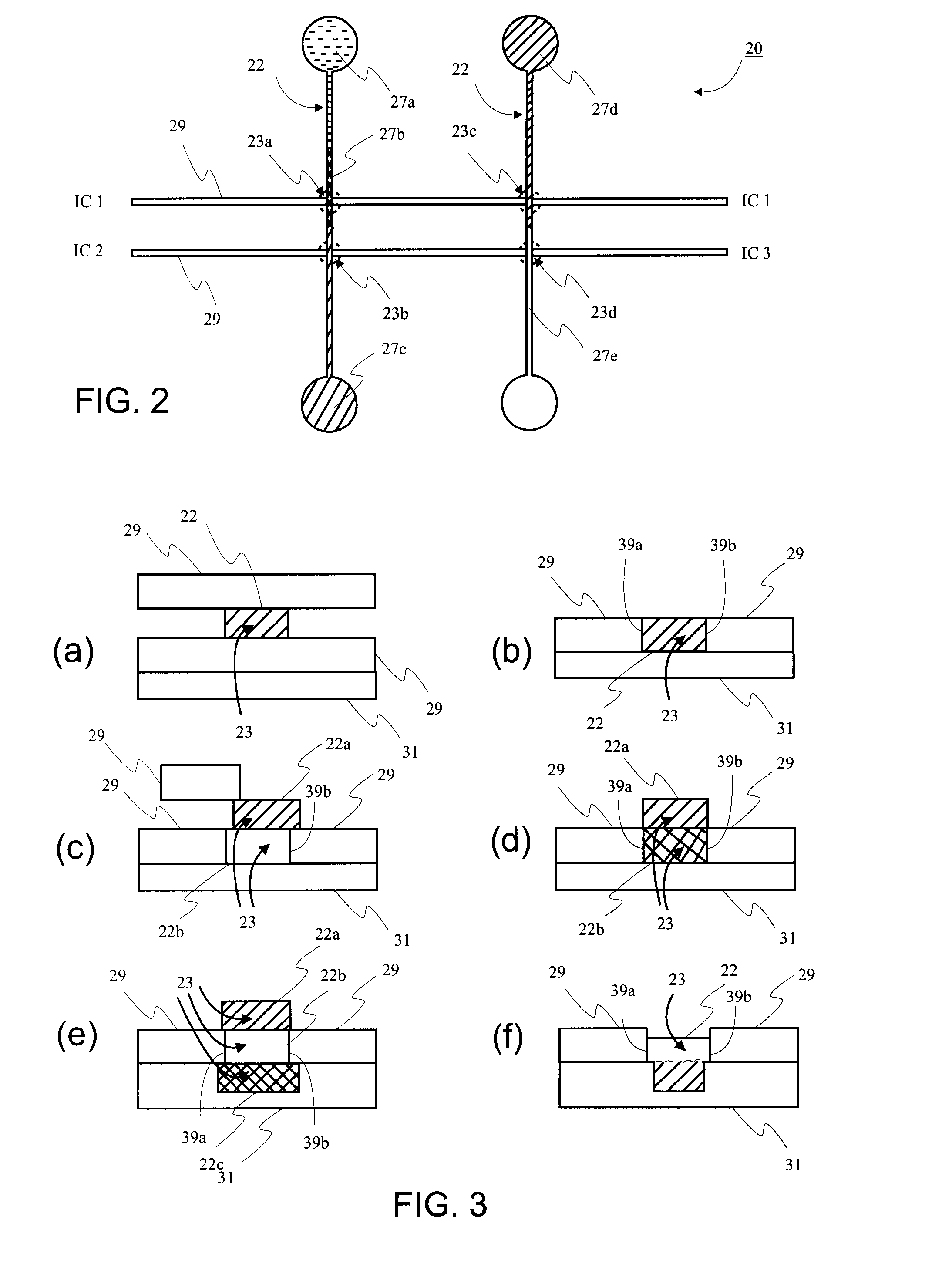
The invention relates to providing detection of an exposure to a physical or chemical phenomenon and revealing information as a response to the exposure. A microfluidic device (20) comprises a microchannel (22) filled at least partly with at least one substance and a conductor (29) providing an intersection area (23a-23d) with the microchannel (22). As a result of exposure to the physical or chemical phenomenon directed to the microchannel (22) or to the substance in the microchannel (22) the microfluidic device (20) is arranged to control electromagnetic characteristic of the conductor (29) in the intersection area (23a-23d). An indicator device (45) comprises the microfluidic device (20) that is connected to means for indicating (40) to indicate the exposure to the phenomenon by giving a visual, sound, scent and / or electhcomagnetic indication. Further a method for detecting exposure to a physical or chemical phenomenon and indicating the exposure is presented.

Description

TECHNICAL FIELD OF THE INVENTION[0001]This invention relates to a device that reveals information as a response to a physical or chemical phenomenon being exposed to the device. More particularly, the invention relates to a microfluidic device that responds to an exposure caused by the phenomenon by generating a response, an indicator device that upon exposure indicates information thereof, and a method of detecting such a phenomenon and indicating information thereof.BACKGROUND OF THE INVENTION[0002]Security of the packages is important, since product counterfeiting is a multi billion business and the brand owners lose annually large sums of money with counterfeit products. For example in the US alone more than 1.2 billion DVDs are sold every year. In packages, the most common security solution is the hologram, which is however relatively easy to counterfeit. Typical application areas for holograms are e.g. tamper evidence, brand protection and authentication.[0003]Monitoring of pr...

Claims


Application Information

Patent Timeline
IPC IPC(8): G01N33/02G08B21/18G01N33/15
CPCG09F3/03G06F3/03
Inventor KANSAKOSKI, MARKKUKEMPPAINEN, ANTTI
Owner TEKNOLOGIAN TUTKIMUSKESKUS VTT OY
Learn More