Method for detecting the state of an electrical protection appliance in an electrical installation and detection device implementing said method

a technology for protecting appliances and electrical installations, applied in the direction of electrical equipment, circuit interrupter testing, instruments, etc., can solve the problems of electrical protection appliance damage, electrical protection appliance open or closed state, etc., to achieve cost-effectiveness, reduce overall dimensions, and optimise design and the cost of electrical protection appliances

Active Publication Date: 2021-11-30
SOCOMEC
View PDF8 Cites 1 Cited by
  • Summary
  • Abstract
  • Description
  • Claims
  • Application Information

AI Technical Summary

Benefits of technology

[0013]The present invention aims to overcome these drawbacks by proposing a novel detection method that does away with the need for auxiliary contacts and thus with the cabling inherent to these auxiliary contacts, thereby procuring a more cost-effective and light-weight detection solution, the implementation whereof is simplified and faster, since it no longer requires auxiliary contact cabling, the results obtained for which are inevitabl

Problems solved by technology

This results in the cables heating up and a fire risk, or:a short-circuit, which is an incidental contact between the phase and neutral in a cable or in a faulty load.
If the circuit concerned is not immediately broken, this would result in damage to the installation and electrocution risks for individuals.
This auxiliary contact cabling solution has drawbacks in terms of implementation costs, safety and reliability, in particular in the case of an electrical installation comprising a plurality of protection appliances.
More specifically, the operation of cabling the auxiliary contacts involves adding numerous additional cables in the switchboards, which is a complex, tedious and expensive operation capable of leading to errors which would falsify the information collected.
Moreover, these additional cables and these auxiliary contacts occupy a large amount of space in the electrical cabinets, which must be dimensioned accordingly.
Finally, equipping electrical protection appliances with auxiliary contacts increases the manufacturing cost thereof.
This solution proposes a very incomplete diagnostic for the installation that can even be dangerous to individuals since c

Method used


Image

  • Method for detecting the state of an electrical protection appliance in an electrical installation and detection device implementing said method
  • Method for detecting the state of an electrical protection appliance in an electrical installation and detection device implementing said method
  • Method for detecting the state of an electrical protection appliance in an electrical installation and detection device implementing said method

Examples


Embodiment Construction

[0050]In the example embodiments shown, identical elements or parts bear the same reference numerals.

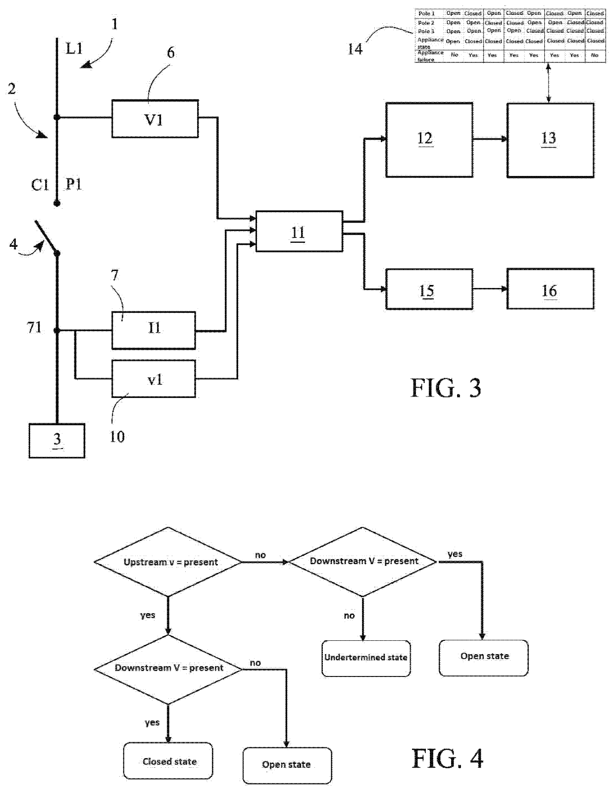
[0051]The method for detecting the open or closed state of a protection appliance according to the invention differs from that of the prior art by the absence of auxiliary contacts and the cabling associated with said auxiliary contacts.

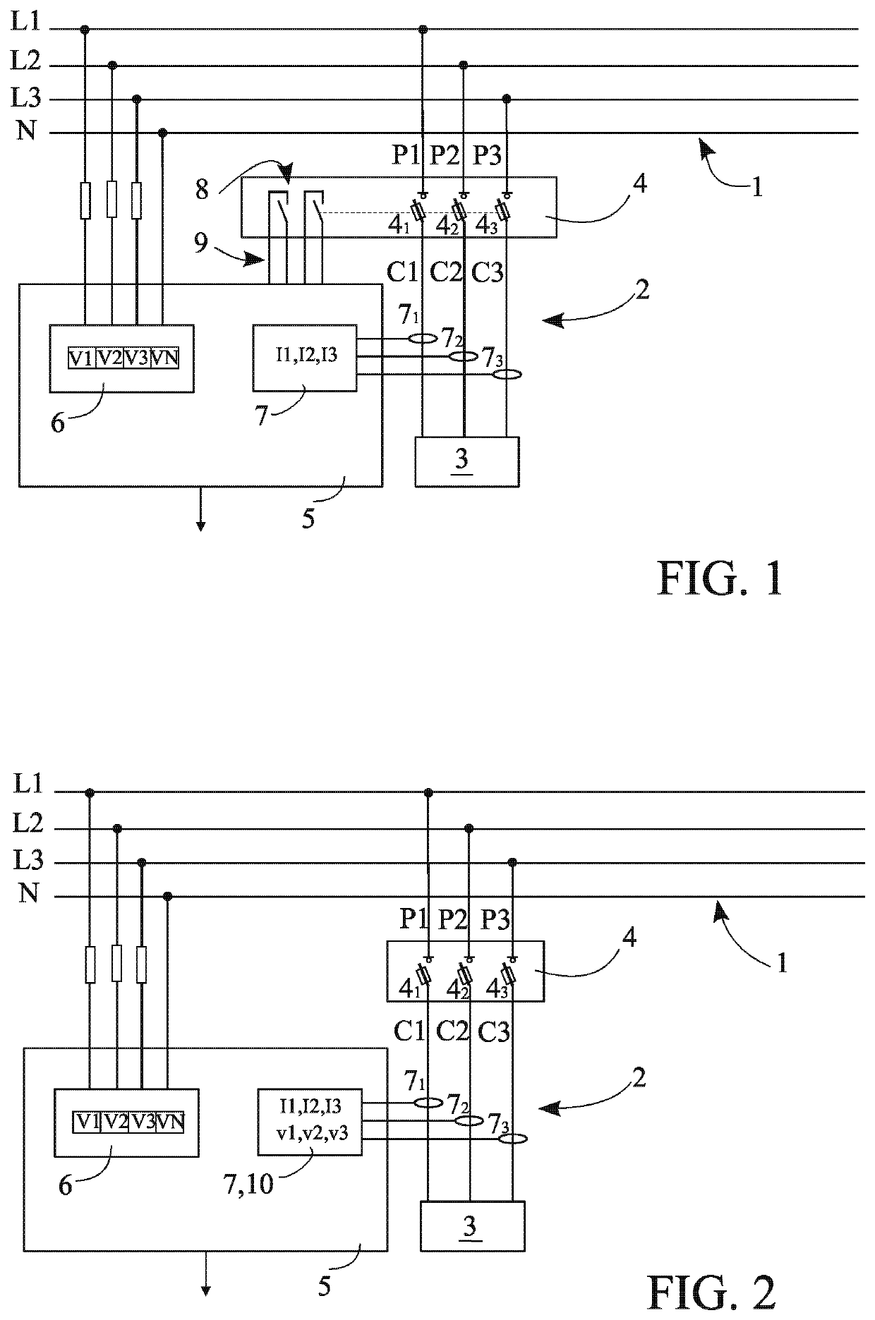
[0052]In order to better understand the advantages of the present invention, FIG. 1 diagrammatically shows an electrical installation of the prior art comprising an electrical power network 1 provided with three phases L1, L2, L3 and one neutral N, from which a network branch 2 is branched in order to supply an energy-consuming load 3, via an electrical protection appliance 4 such as a circuit breaker, however is not limited thereto. The load 3 is a three-phase load powered by three conductors C1, C2, C3 branched off of the phases L1, L2, L3 of the network 1. In such a case, the protection appliance 4 comprises three poles P1, P2, P3, each provided wi...


PUM


Abstract

A method for detecting the open or closed state of a protection appliance in an electrical installation including a voltage detector upstream of the protection appliance and a voltage detector downstream thereof, in which the voltage data provided by the voltage detectors is used to obtain information regarding the presence or absence of voltage upstream and downstream of the protection appliance, a correlation is established between the voltage data, and it is determined whether the protection appliance is in an open state, in a closed state, in an abnormal state or in an undetermined state. The current data provided by the current detectors can also be used to determine the cause of the tripping of the protection appliance, and to thereby obtain a full, precise and real-time diagnostic for the operation of the electrical installation.

Description

TECHNICAL FIELD[0001]The present invention relates to a method for detecting the open or closed state of an electrical protection appliance in an electrical installation, said installation comprising at least one upstream voltage detector and one downstream voltage detector respectively disposed upstream and downstream of said protection appliance.[0002]It further relates to a device for detecting the open or closed state of an electrical protection appliance in an electrical installation allowing the aforementioned method to be implemented.BACKGROUND ART[0003]The term “electrical protection appliance” denotes any appliance or member of the circuit breaker, fuse, fused interrupter switch, electromechanical relay, or a similar type, the main function whereof is to protect individuals, loads and electric circuits by automatically cutting the current passing therethrough in the event of a fault such as:[0004]an overload arising when the power demanded by the circuit exceeds the capacit...

Claims


Application Information

Patent Timeline
IPC IPC(8): G01R31/327H01H71/04G01R19/25
CPCG01R31/327G01R19/2513H01H71/04H01H2071/042
Inventor CAPOT, MARCHERR, PIERRE-HENRIKERN, CHRISTIAN
Owner SOCOMEC
Why Eureka
Try Eureka