Fundus camera

a fundus camera and camera body technology, applied in the field offundus cameras, can solve the problems of loss of light, large size of fundus cameras, complex configuration of fundus cameras, etc., and achieve the effect of efficiently indicating an internal fixation target and loss of light reflected

Inactive Publication Date: 2010-09-21
CANON KK
View PDF7 Cites 7 Cited by
  • Summary
  • Abstract
  • Description
  • Claims
  • Application Information

AI Technical Summary

Benefits of technology

[0011]The present invention is directed to a fundus camera configured to use a single imaging unit for both observing and photographing a subject's eye fundus, and to be capable of reducing, when photographing the fundus, loss of the amount of light reflected from the fundus, and efficiently indicating an internal fixation target.

Problems solved by technology

Accordingly, the dual-use type fundus camera discussed in Japanese Patent Application Laid-Open No. 9-66030 has problems in that the configuration of the fundus camera is complex, and that the size of the fundus camera is large.
Consequently, a loss of the amount of light occurs.
In addition, no optical finder is provided in the fundus camera.

Method used


Image

  • Fundus camera
  • Fundus camera
  • Fundus camera

Examples


Embodiment Construction

[0021]Various exemplary embodiments, features, and aspects of the invention will be described in detail below with reference to the drawings.

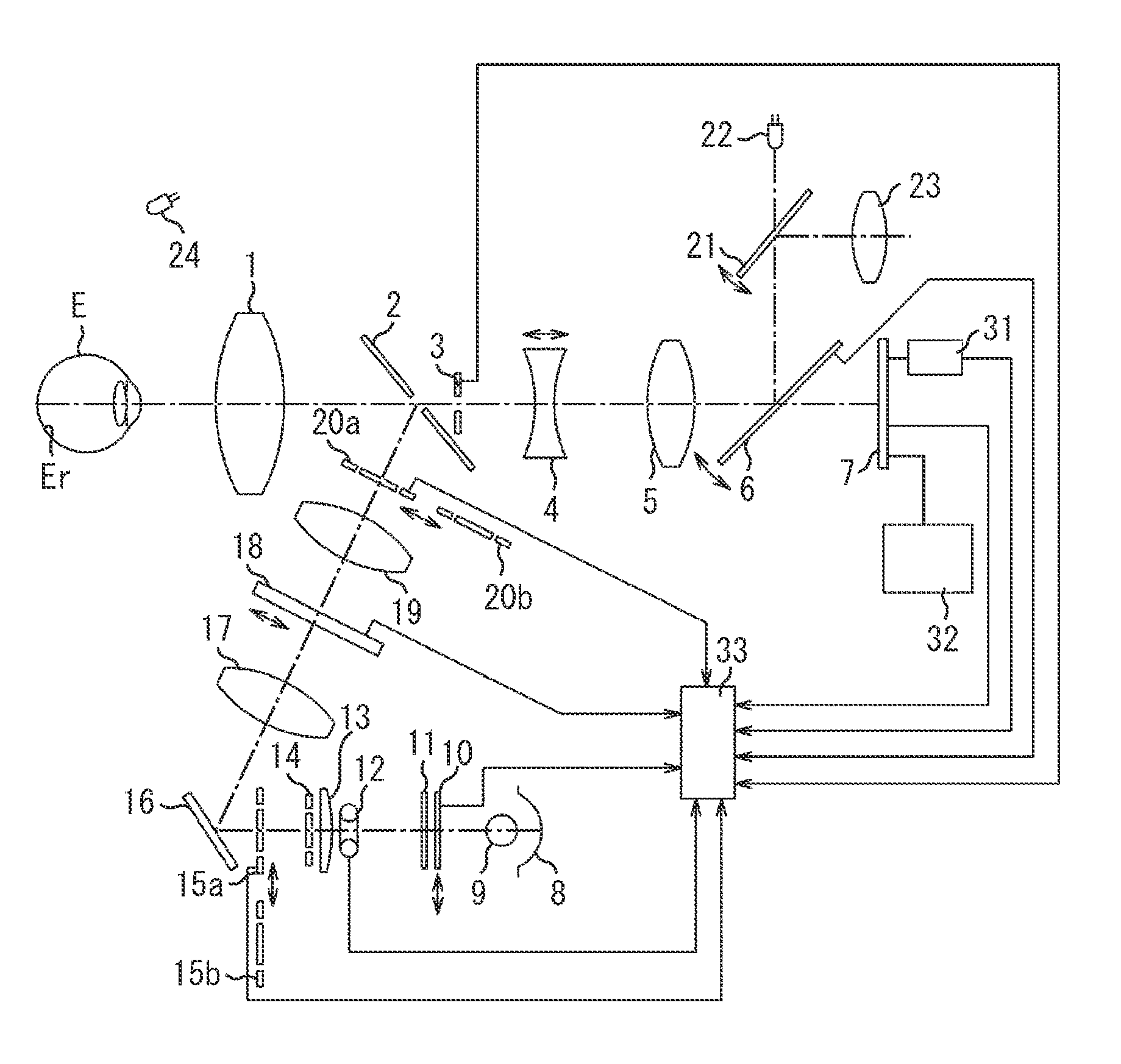
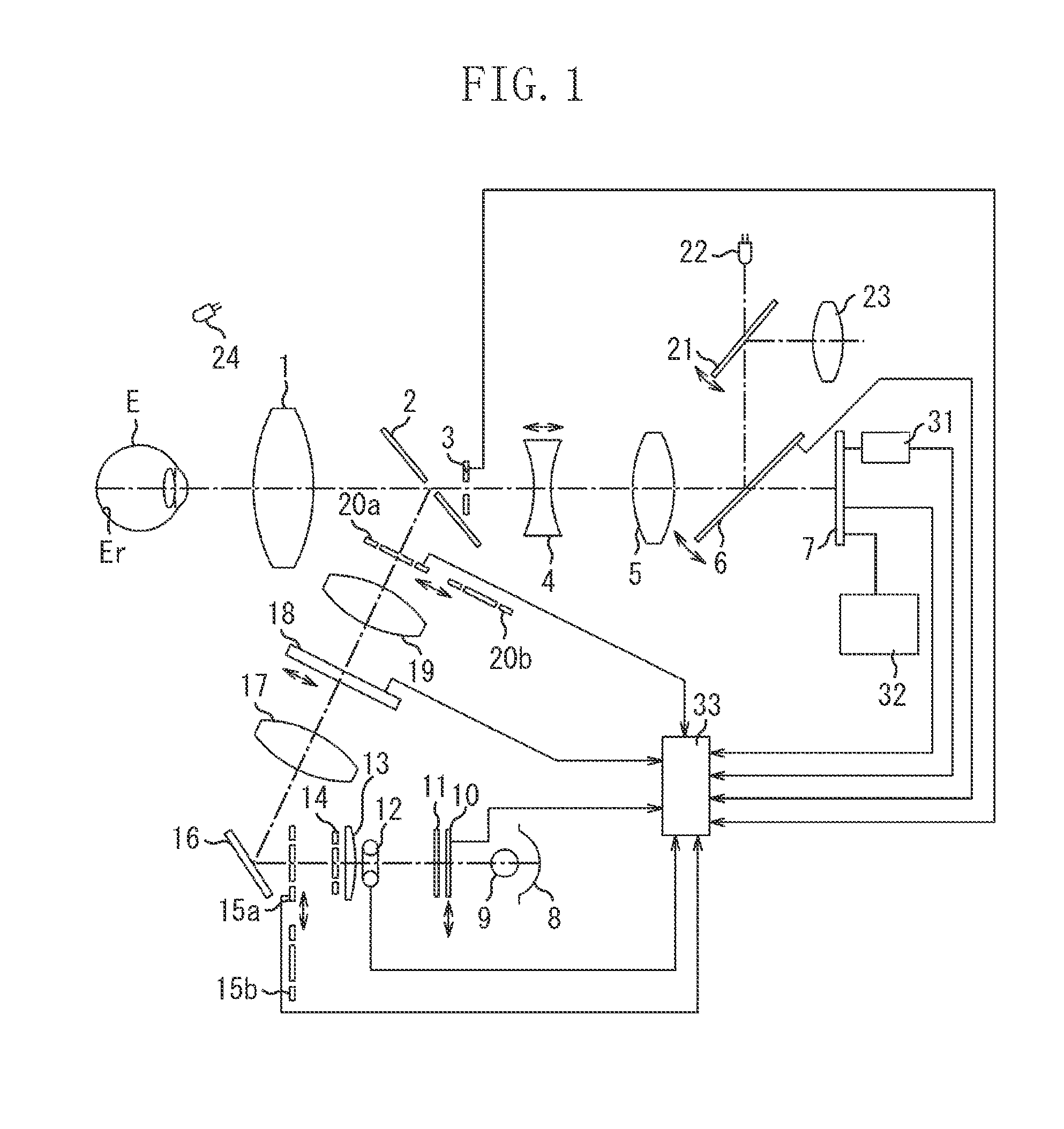
[0022]FIG. 1 illustrates a configuration of a fundus camera of the dual-use type usable for both mydriatic photographing and non-mydriatic photographing according to an exemplary embodiment of the present invention. In an observing / photographing optical system in front of a subject's eye E, an objective lens 1, a perforated mirror 2, a photographing diaphragm 3, a focusing lens 4, an imaging lens 5, a quick-return mirror 6, and an imaging unit 7 are sequentially arranged. The focusing lens 4 is a focusing unit for focusing the optical system on a fundus Er of the subject's eye E. The quick-return mirror 6 is an optical path splitting unit constructed to be retreatable from an optical path. The imaging unit 7 has sensitivity to both light of a visible light region and near-infrared light of an invisible light region.

[0023]An illumination optical...


PUM


Abstract

A fundus camera includes an optical path splitting unit arranged between a focusing unit and an imaging unit. The splitting unit has characteristics adapted to reflect light of a visible light region and to transmit near-infrared light. The splitting unit retreats from an optical path when a still fundus image is photographed. A quick-return mirror having such characteristics is used as the splitting unit. When near-infrared illumination light having a wavelength of about 850 nm is used, such light can be incident upon the imaging unit without loss of the amount of light. Visible light output from an internal fixation target is projected onto a subject's eye. A cornea diaphragm and a crystalline lens diaphragm are used for observing a fundus with invisible light. Each of the cornea diaphragm and crystalline lens diaphragm can be changed to another one having a different diameter.

Description

BACKGROUND OF THE INVENTION[0001]1. Field of the Invention[0002]The present invention relates to a fundus camera for observing a fundus of a subject's eye with near-infrared light or visible light.[0003]2. Description of the Related Art[0004]Fundus cameras for observing and photographing a subject's eye fundus are roughly classified into a mydriatic type fundus camera to be used by applying a mydriatic to a subject's eye, and a non-mydriatic type fundus camera to be used without applying a mydriatic to a subject's eye. The former type fundus camera is used mainly by ophthalmologists. Usually, when a subject's eye fundus is photographed using the former type fundus camera, a plurality of images of the fundus is taken not only by a color photographing technique but also by various techniques, such as a fluorescent photographing technique and a special filter photographing technique. The latter type fundus camera is used mainly by doctors for medical check-up or physicians. When a subj...

Claims


Application Information

Patent Timeline
Patent Type & Authority Patents(United States)
IPC IPC(8): A61B3/10A61B3/14
CPCA61B3/14
Inventor ITOH, HIROSHITANAKA, SHINYATAKAI, MOTOYA
Owner CANON KK
Why Eureka
Try Eureka