
Automatic subterranean watering system with refill indicator and gripping mechanism

a subterranean watering system and automatic technology, applied in the field of plant pots, can solve the problems of not providing an efficient and operator-friendly way to indicate the present water level of the system, and the system does not lend itself to efficient and easy hand removal from the pot as desired by the operator, so as to achieve the effect of convenient removal of the system and easy removal

Active Publication Date: 2015-04-09
WATSON MILTON B
View PDF12 Cites 8 Cited by
  • Summary
  • Abstract
  • Description
  • Claims
  • Application Information

AI Technical Summary

Benefits of technology

The present invention is an automatic watering system with a refill indicator that can show the water level in the system. It can also be used as a water filling port for adding water to the system. The refill indicator can be easily removed from the system and used as a water feed reservoir. The system includes a seal that is activated by the refill indicator and a gripping mechanism for easy removal from a flower pot. The system does not require complicated sensors and is easy to remove from a larger container. The technical effects of the invention are efficient water level indication, easy removal from a container, and effective water feeding without complicated sensors.

Problems solved by technology

However, these improved plant watering devices may require sensors (i.e. a porous sensing element, a dryness sensor, a hydrophilic polyethylene sensor, a hydrophilic sensor, etc.) to trigger the release of water to the roots of the plant.
As described in U.S. Pat. No. 7,703,240, none of these prior art plant watering devices teaches an automatic watering system for a plant that allows the root system to dehydrate before another watering cycle is initiated.
Meanwhile, while the plant water device of U.S. Pat. No. 7,703,240 allows for the root system to dehydrate before another water cycle is initiated, the device does not provide for an efficient and operator-friendly way to indicate the present water level as it exists within the device.
Further, if the automatic watering system is positioned within another container, such as a common plastic, clay or ceramic pot, the system does not lend itself for efficient and easy removal by hand from the pot as desired by an operator.

Method used


Image

  • Automatic subterranean watering system with refill indicator and gripping mechanism
  • Automatic subterranean watering system with refill indicator and gripping mechanism
  • Automatic subterranean watering system with refill indicator and gripping mechanism

Examples


Embodiment Construction

[0020]Reference will now be made in detail to the preferred embodiments of the invention, examples of which are illustrated in the accompanying drawings. While the invention will be described in conjunction with the preferred embodiments, it will be understood that they are not intended to limit the invention to those embodiments. On the contrary, the invention is intended to cover alternatives, modifications and equivalents, which may be included within the spirit and scope of the invention as defined by the appended claims. The figures are illustrative of an embodiment of an automatic watering system 100. Similar reference numerals are used in the various figures to represent like parts throughout the several views.

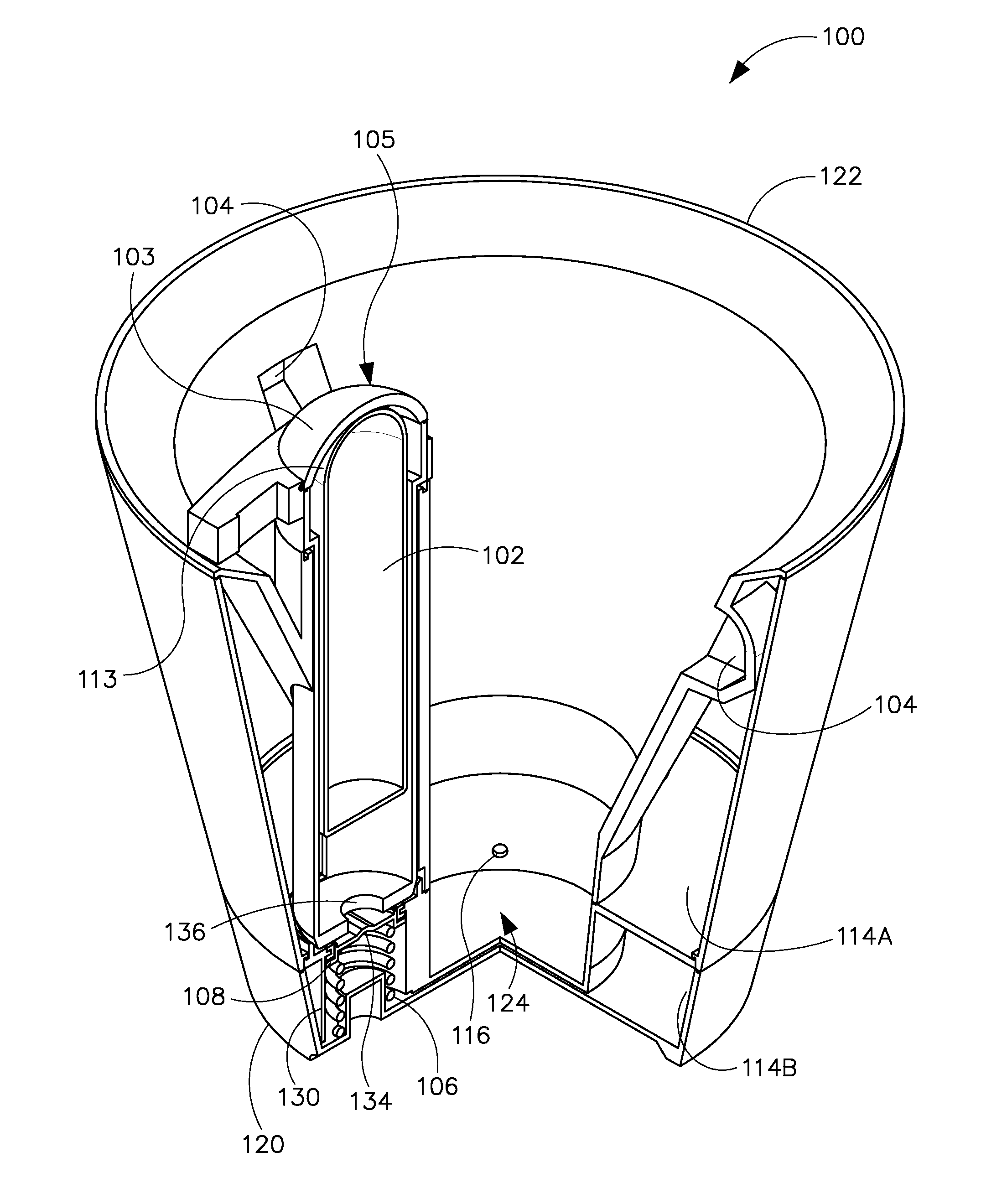
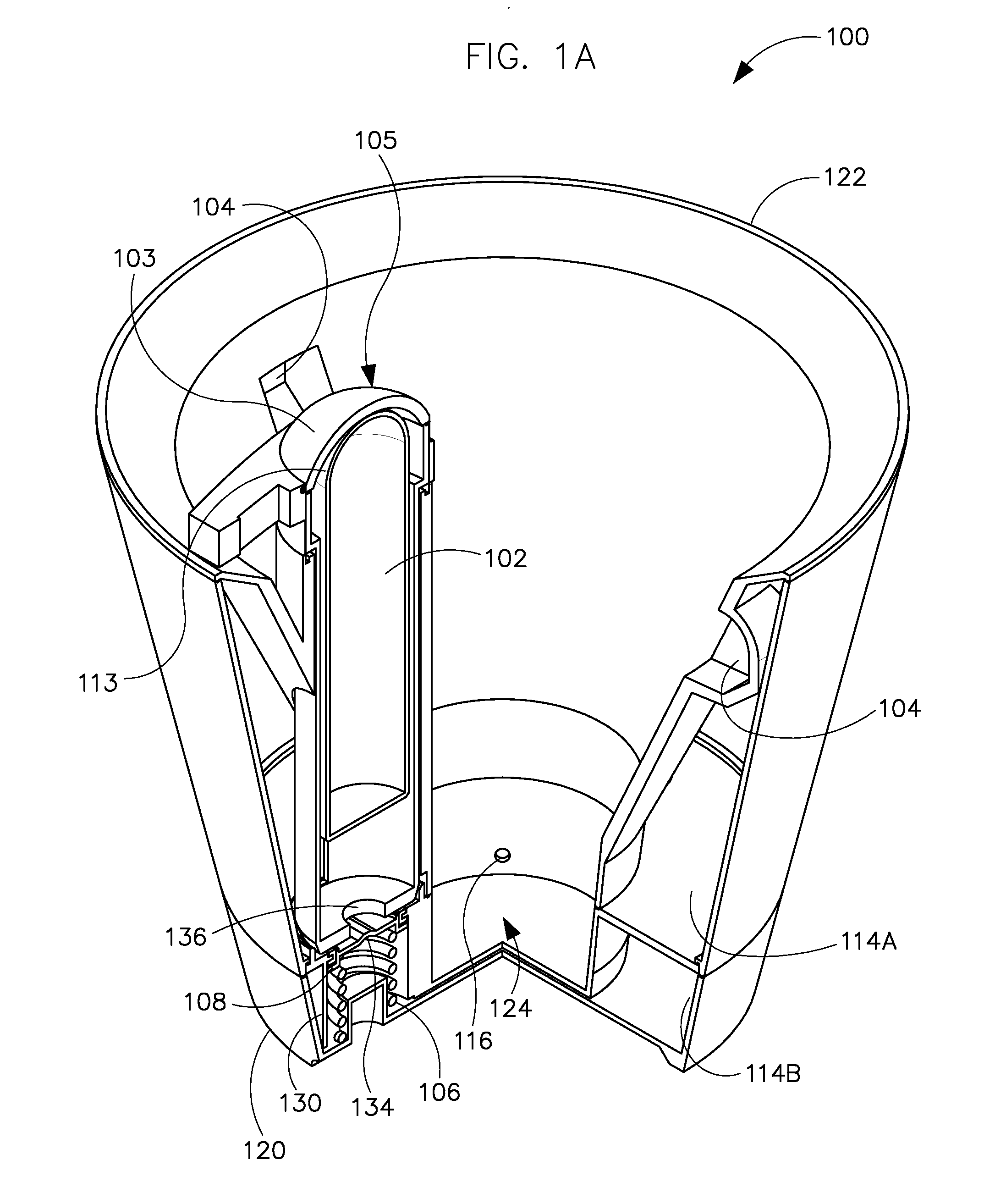
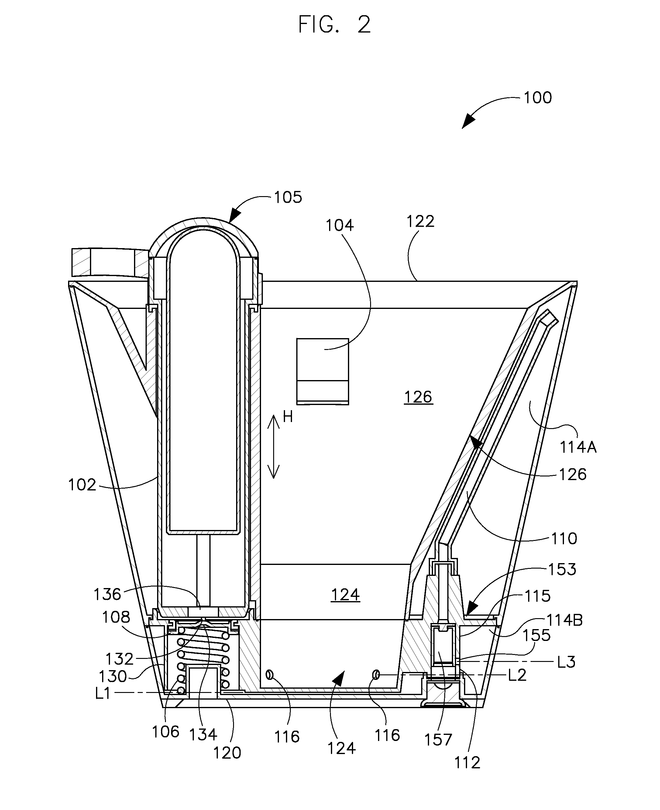
[0021]Referring now to FIG. 1A, a perspective view of an embodiment of an automatic watering system 100 with a refill indicator 105 and gripping mechanisms 104 according to the present invention is illustrated. In addition to the refill indicator 105 and gripping mechan...


PUM


Abstract

An automatic watering system includes a water storage reservoir and a water feed reservoir positioned elevationally below the water storage reservoir. The water feed reservoir has a plurality of water feed apertures aligned substantially horizontally for allowing water to pass from the water feed reservoir to outside of the water feed reservoir. The water feed reservoir is in fluid communication with the water storage reservoir via a water tube with a biased seal and via an air return conduit which has a float valve. The water storage reservoir is in fluid communication with the refill indicator for indicating a water level present within the water storage reservoir. The refill indicator includes a float body that tracks the water level within the water storage reservoir. The automatic watering system may also include a gripping mechanism positioned near a top portion of the water storage reservoir.

Description

BACKGROUND OF THE INVENTION[0001]1. Technical Field[0002]This invention relates generally to the field of plant pots, and more particularly to a self-watering plant pot.[0003]2. Prior Art[0004]Numerous innovations for plant watering devices have been provided in the prior art. For example, as mentioned in the related art section of U.S. Pat. No. 7,703,240, many improvements to plant watering devices include no moving parts. However, these improved plant watering devices may require sensors (i.e. a porous sensing element, a dryness sensor, a hydrophilic polyethylene sensor, a hydrophilic sensor, etc.) to trigger the release of water to the roots of the plant.[0005]As described in U.S. Pat. No. 7,703,240, none of these prior art plant watering devices teaches an automatic watering system for a plant that allows the root system to dehydrate before another watering cycle is initiated. Meanwhile, while the plant water device of U.S. Pat. No. 7,703,240 allows for the root system to dehydr...

Claims


Application Information

Patent Timeline
IPC IPC(8): A01G27/00
CPCA01G27/005A01G27/008A01G27/003
Inventor WATSON, MILTON B.COFFIN, TRISTRAM ZANE
Owner WATSON MILTON B
Learn More