High-efficiency dual-stack molten carbonate fuel cell system

a fuel cell and molten carbonate technology, applied in the direction of fuel cells, electrochemical generators, electrical equipment, etc., can solve the problems of low equipment cost, single stack often outweighs the operating and fuel utilization efficiency of multi-stack assemblies, and achieves the effect of improving efficiency

Active Publication Date: 2011-11-22
FUELCELL ENERGY INC
View PDF46 Cites 21 Cited by
  • Summary
  • Abstract
  • Description
  • Claims
  • Application Information

AI Technical Summary

Problems solved by technology

However, the additional fuel cell stacks used in these systems for utilizing the unspent fuel in the anode exhaust of the first fuel cell stack result in significant increases in equipment and maintenance costs.
The equipment cost of using low temperature fuel cell stacks in the '971 patent and in the '740 application instead of a single stack often outweighs the operating and fuel utilization efficiencies of multi-stack assemblies.

Method used


Image

  • High-efficiency dual-stack molten carbonate fuel cell system
  • High-efficiency dual-stack molten carbonate fuel cell system
  • High-efficiency dual-stack molten carbonate fuel cell system

Examples


Embodiment Construction

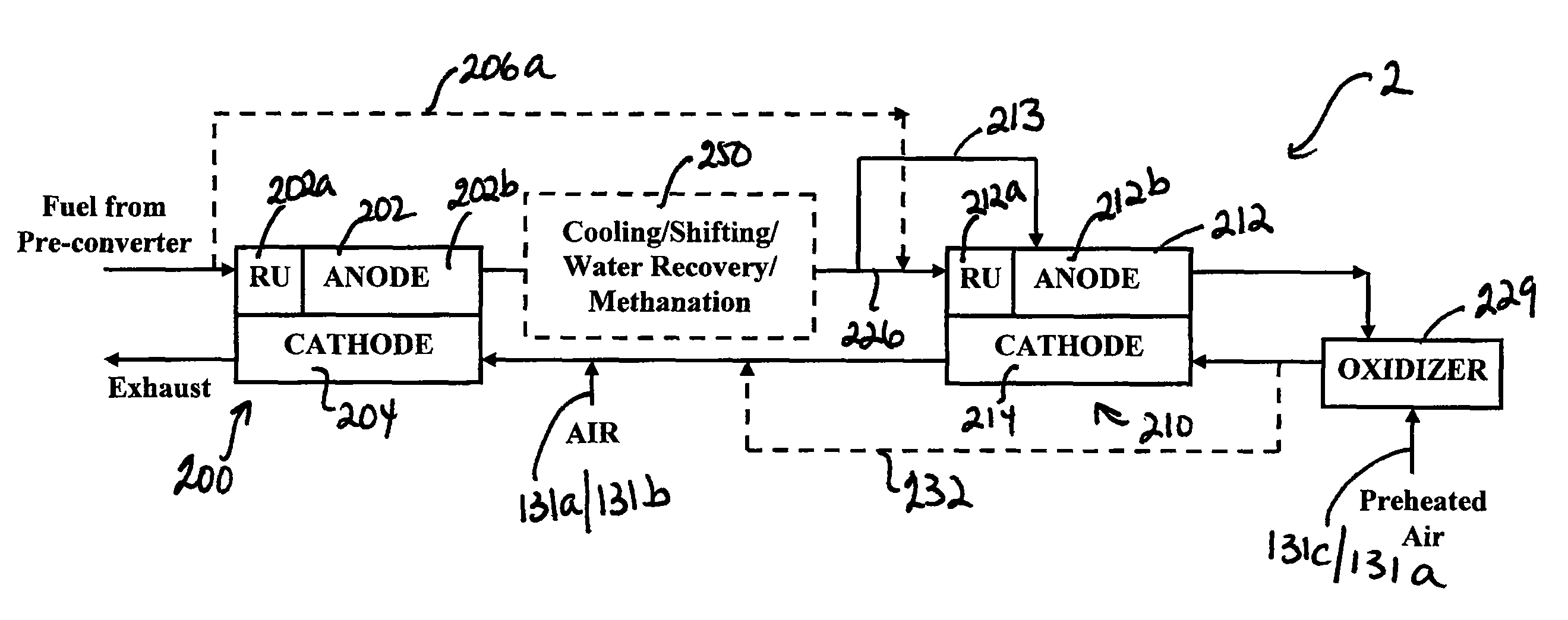
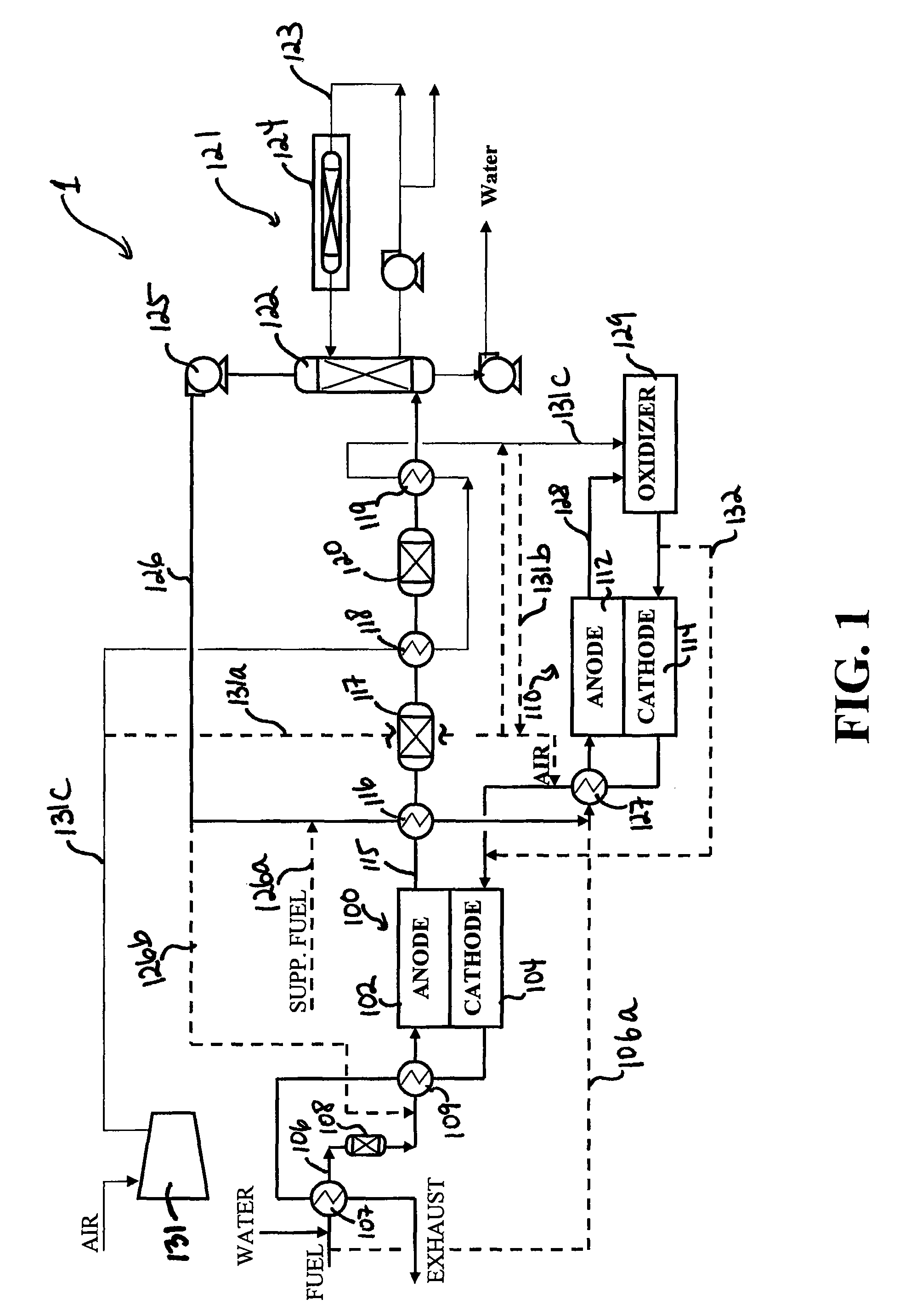
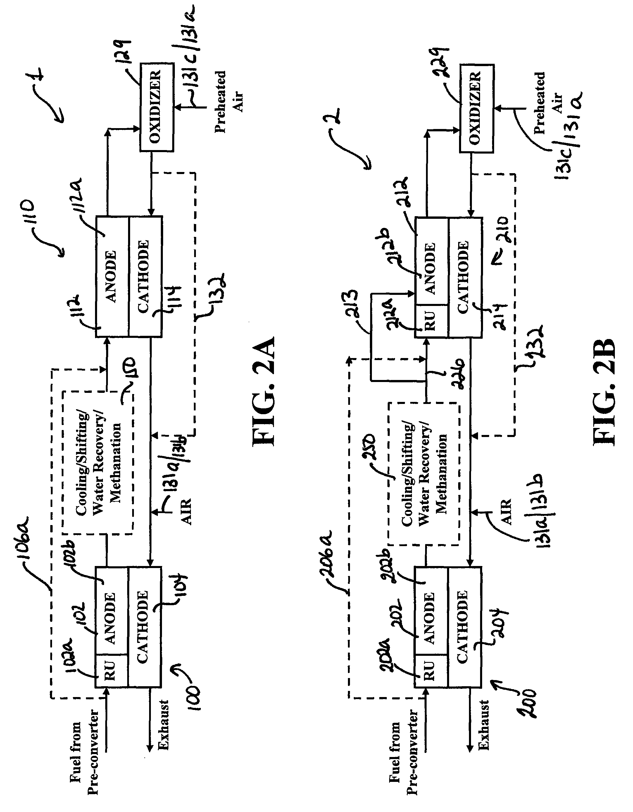
FIG. 1 shows a dual-stack fuel cell system 1 including two molten carbonate fuel cell stacks connected in series. The system 1 shown in FIG. 1 has improved performance efficiencies, and in particular, higher fuel utilization and power output, compared to conventional single-stack systems, and also provides manufacturing and operational cost efficiencies compared to conventional multi-stack fuel cell systems. The improved performance and cost efficiencies of the system 1 will be described in more detail herein below.

As shown, the system 1 comprises a first molten carbonate fuel cell stack 100 including a first anode side 102 and a first cathode side 104 separated by a molten carbonate electrolyte (not shown), and a second molten carbonate fuel cell stack 110 including a second anode side 112 and a second cathode side 114 separated by a molten carbonate electrolyte matrix (not shown). The first anode side 102 is adapted to receive fuel and to output first anode exhaust, while the seco...


PUM

PropertyMeasurementUnit
chemical energyaaaaaaaaaa
electrical energyaaaaaaaaaa
electrically conductiveaaaaaaaaaa

Abstract

A dual stack fuel cell system comprising a first fuel cell stack comprising a first anode side, adapted to receive fuel and to output a first anode exhaust, and a first cathode side, a second fuel cell stack comprising a second anode side, adapted to receive processed anode exhaust derived from the first anode exhaust and to output a second anode exhaust, and a second cathode side, adapted to receive oxidant gas and to output a first cathode exhaust, wherein the first cathode side receives at least the first cathode exhaust outputted from the second cathode side; and wherein the first fuel cell stack includes indirect internal reforming and the second fuel cell stack may not include any indirect internal reforming.

Description

BACKGROUND OF THE INVENTIONThis invention relates to fuel cell power production systems and, in particular, to dual-stack molten carbonate fuel cell systems.A fuel cell is a device which directly converts chemical energy stored in hydrocarbon fuel into electrical energy by means of an electrical reaction. Generally, a fuel cell comprises an anode and a cathode separated by an electrolyte, which serves to conduct electrically charged ions. In order to produce a useful power level, a number of individual fuel cells are stacked in series with an electrically conductive separator plate between each cell.In internally reforming fuel cells, a steam reforming catalyst is placed within the fuel cell stack to allow direct use of hydrocarbon fuels such as methane, coal gas, etc. without the need for expensive and complex external reforming equipment. In a reforming reaction, fuel cell produced water and heat are used by the reforming reaction, and the fuel is internally reformed to produce hy...

Claims


Application Information

Patent Timeline
Patent Type & Authority Patents(United States)
IPC IPC(8): H01M8/06
CPCH01M8/04291H01M8/04701H01M8/04753H01M8/0612H01M8/0637H01M8/249H01M2008/147Y02E60/50Y02E60/526H01M8/145
Inventor JAHNKE, FRED C.FAROOQUE, MOHAMMADGHEZEL-AYAGH, HOSSEIN
Owner FUELCELL ENERGY INC
Why Eureka
Try Eureka