Kinematic wellplate mounting method

a technology of kinematic wellplates and mounting methods, applied in the direction of analytical using chemical indicators, laboratory glassware, instruments, etc., can solve the problems of adverse effects of second/final measurement results, and achieve the effect of reducing the range of motion

Active Publication Date: 2011-11-29
CORNING INC
View PDF22 Cites 8 Cited by
  • Summary
  • Abstract
  • Description
  • Claims
  • Application Information

AI Technical Summary

Benefits of technology

[0012]Another embodiment of the present invention is a microplate restraining mechanism whose supports contain one or more mating features that are capable of interacting with one or more respective microplate mating feature(s). The mechanism may additionally exhibit one or more guide pins located on a periphery or outer edge of the nesting receptacle. These guide pins are capable of aligning a microplate into a predefined position with respect to the supports. As such, a preferred embodiment of the mechanism of the present invention has one or more pair(s) or set(s) of guide pins located on the corners or sides of the nesting receptacle such that the guide pins are capable of aligning at least one microplate side or corner. Guide pins may be advantageous in manual or robotic movement and manipulation of the microplate to assist in precise positioning of the microplate. The guide pins are preferably shaped to assist in the gradual positioning of the microplate such that sudden movements of the microplate are avoided further preventing disruption of the contents on the microplate sample surface(s). Though any shape or combinations of shapes are suitable, a preferred embodiment has guide pins with a cylindrical shaped base at a point of attachment on the periphery of the nesting receptacle. The cylindrical shape tapers upward to a conical shape where a microplate is capable of being initially received.
[0014]In another aspect, the present invention includes a microplate assembly comprising a restraint mechanism having a base with at least one surface defining a nesting receptacle for a microplate, at least three supports projecting from the base to support the microplate, and a microplate located within the nesting receptacle contacting the supports. In one embodiment of the present invention, at least six constraints are utilized in order to maintain positional stability of the microplate in the X, Y, and Z planes; three microplate mating features contact / engage with three mating features of the supports generating six point contacts between the microplate and the base of the restraint mechanism. The microplate of this assembly is further capable of comprising at least one well having at least one sensor located within a bottom surface of the well.
[0016]In addition, an embodiment of the mechanism of the present invention is shaped and configured to enable robotic access to the microplate mount / stage area, where the microplate is positioned into the base without requiring cumbersome robotic arm manipulation.
[0018]It is accordingly desirable to provide a mechanism that reduces the range of motion required in active repositioning of a microplate. Moreover, it is desireable to have a mechanism that limits the movement of the microplate while restrained in X, Y, and Z planes of a defined position upon successive mounts. It is further advantageous for the microplate restraining mechanism to be consistent and reproducible. Depending on the assay and the detection equipment, it may be desireable that successive positioning of a microplate within a stage not vary by more than 1 micron translation or 20 microRadians rotation. Furthermore, a mount design capable of allowing possible robotic manipulation of the microplate is beneficial to future high-throughput analysis. Additional advantages of the invention will become apparent after consideration of the ensuing description and the accompanying drawings.

Problems solved by technology

Therefore, the second / final measurement result can be adversely affected by the slightest change, rotational and / or translational, in microplate position between the initial and second / final measurement steps.

Method used


Image

  • Kinematic wellplate mounting method
  • Kinematic wellplate mounting method
  • Kinematic wellplate mounting method

Examples


Embodiment Construction

[0040]In the following detailed description, for purposes of explanation and not limitation, exemplary embodiments disclosing specific details are set forth in order to provide a thorough understanding of the present invention. However, it will be apparent to one having ordinary skill in the art that the present invention may be practiced in other embodiments that depart from the specific details disclosed herein. In other instances, detailed descriptions of well-known devices and methods may be omitted so as not to obscure the description of the present invention.

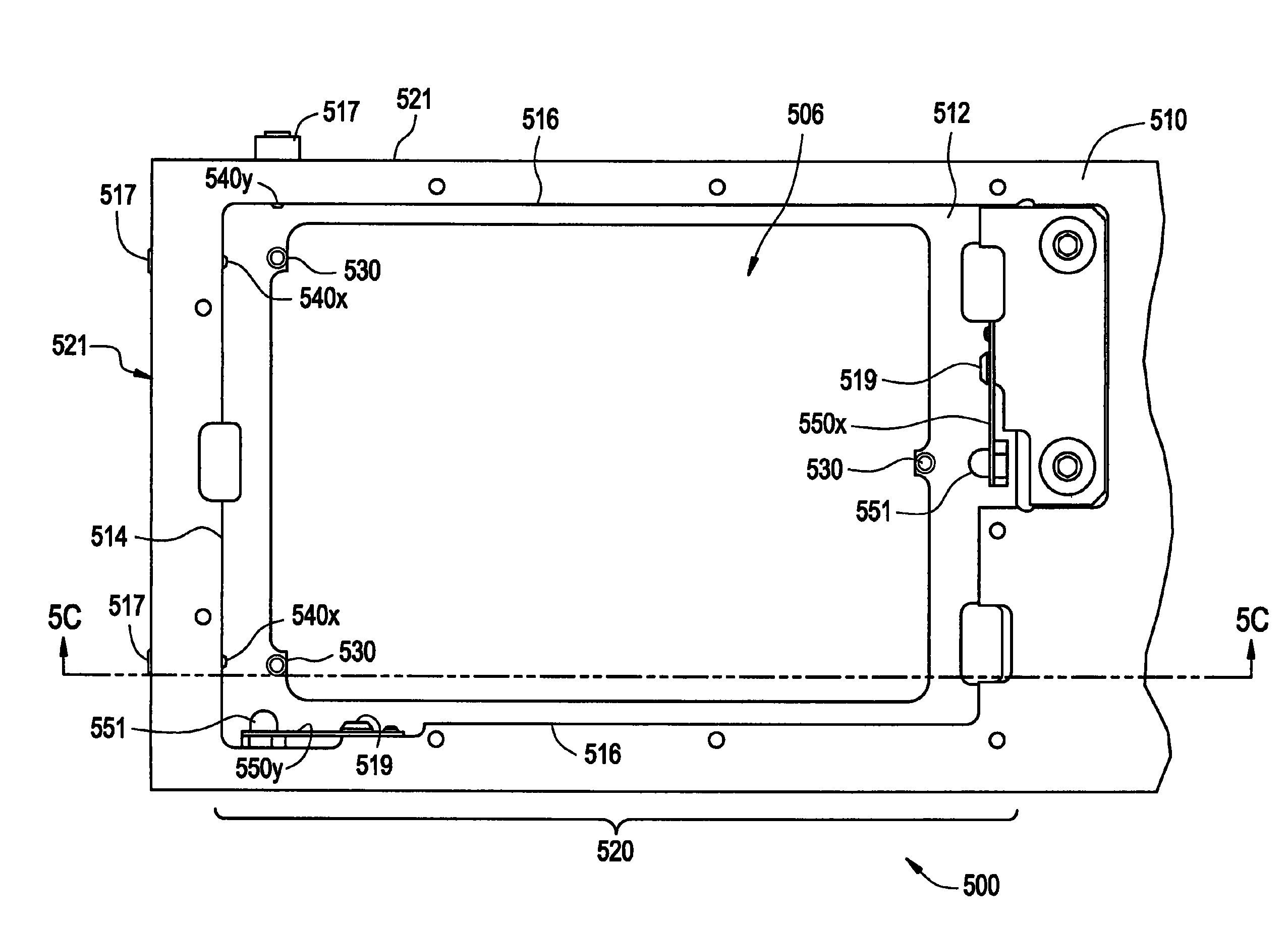
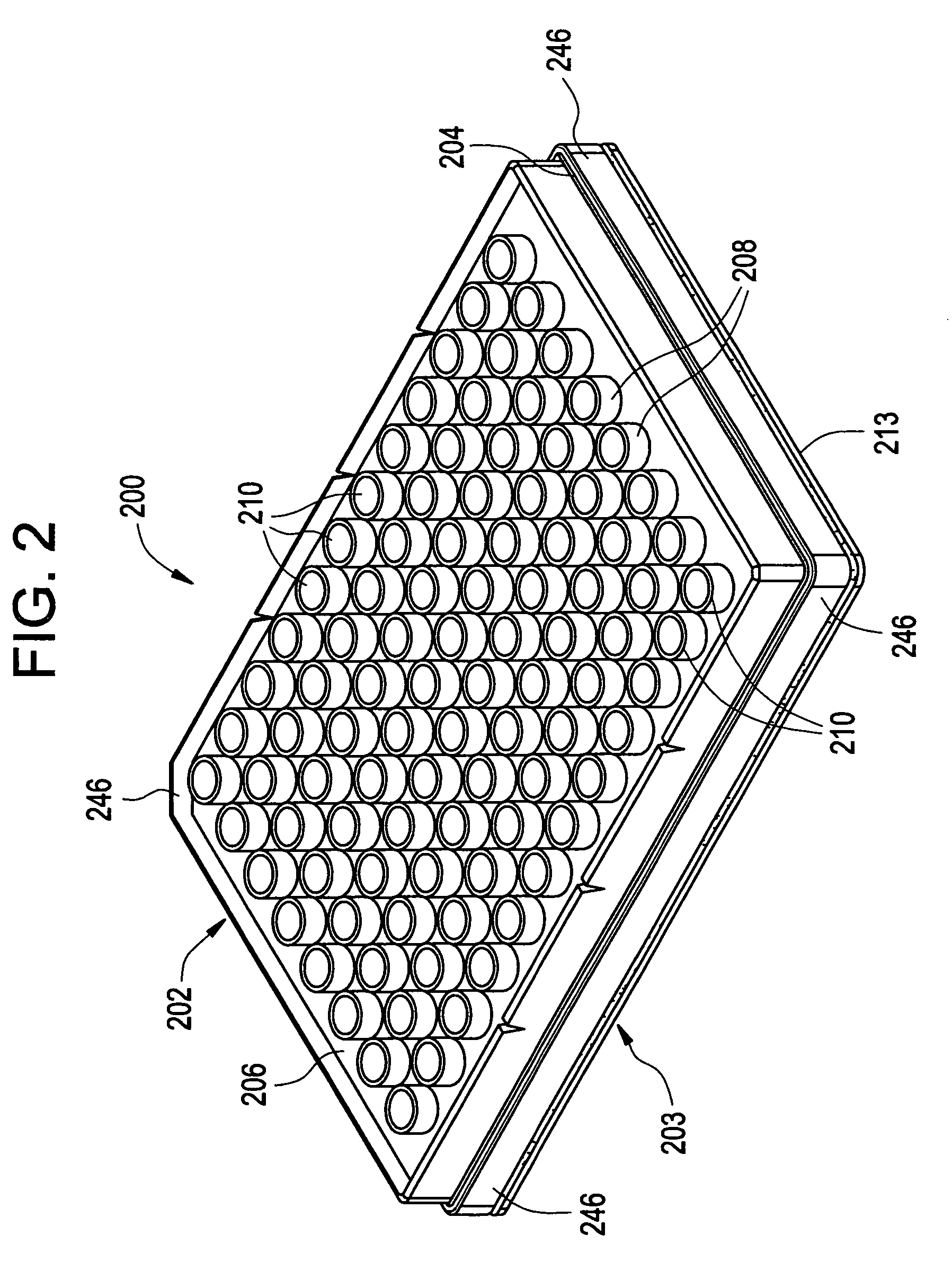
[0041]The restraining mechanism 100 in accordance with one embodiment of the present invention is illustrated in FIG. 1. The mechanism 100 comprises a structure / base 101 having a surface 110, as well as three supports 150 projecting from the base 101 which are capable of supporting a microplate. Two side walls 112 and two end walls 114 intersect in corners 116 to form a rectangular periphery having an opening or a detectio...


PUM


Abstract

A mechanism for positionally restraining a microplate is disclosed. The mechanism is defined by a base having at least one surface with a receptacle for the insertion of a microplate into the base. Supports and / or positioning structures on a surface of the base have point contacts to restrain movement of the microplate in a stable position for repeatable optical detection measurements. The supports and / or positioning structures permit insertion of the microplate for an initial measurement, removal of the microplate for analytical manipulation, and re-insertion of the microplate to an exact position so as to allow analysis of precise comparative measurements by an optical reader.

Description

CROSS-REFERENCE TO RELATED APPLICATIONS[0001]This application claims the benefit of U.S. Application Ser. No. 60 / 701,452 filed on Jul. 20, 2005 and entitled “Kinematic Wellplate Mounting Method” which is incorporated by reference herein in.FIELD OF THE INVENTION[0002]The present invention relates generally to a mechanism for restraining a microplate in a fixed position.BACKGROUND OF THE INVENTION[0003]At the present time, existing technology utilizes various instrumentation to measure photometric properties such as color, absorbance, intensity, and photoluminescence at specific locations on a microplate surface where chemical and biological samples are associated. For example, optical readers are commonly used in biological fields such as genetic research, drug discovery, or diagnostic purposes to detect hundreds or thousands of compounds (e.g., DNA, oligonucleotides, proteins, etc.) typically deposited on a surface of a substrate (e.g., a glass slide) in an array configuration. It ...

Claims


Application Information

Patent Timeline
Patent Type & Authority Patents(United States)
IPC IPC(8): B01L9/00
CPCB01L9/523G01N35/028B01L2200/025G01N2035/0425B01L2300/0829
Inventor COSTELLO, III, JOHN J.POPOLOSKI, MARTIN J.THOMAS, JOHN C.
Owner CORNING INC
Why Eureka
Try Eureka