
Manufacturing method of solar cell module, and solar cell and solar cell module
a solar cell module and manufacturing method technology, applied in the field of solar cell module manufacturing method, can solve the problems of cumbersome work, low filling rate of solar cells b>10/b> to the solar cell module b>20/b>, and reduce the use efficiency of ingots, so as to facilitate the electrical connection work of solar cells.
- Summary
- Abstract
- Description
- Claims
- Application Information
AI Technical Summary
Benefits of technology
Problems solved by technology
Method used
Image

Examples
configuration example 1
1. Configuration of Solar Cell
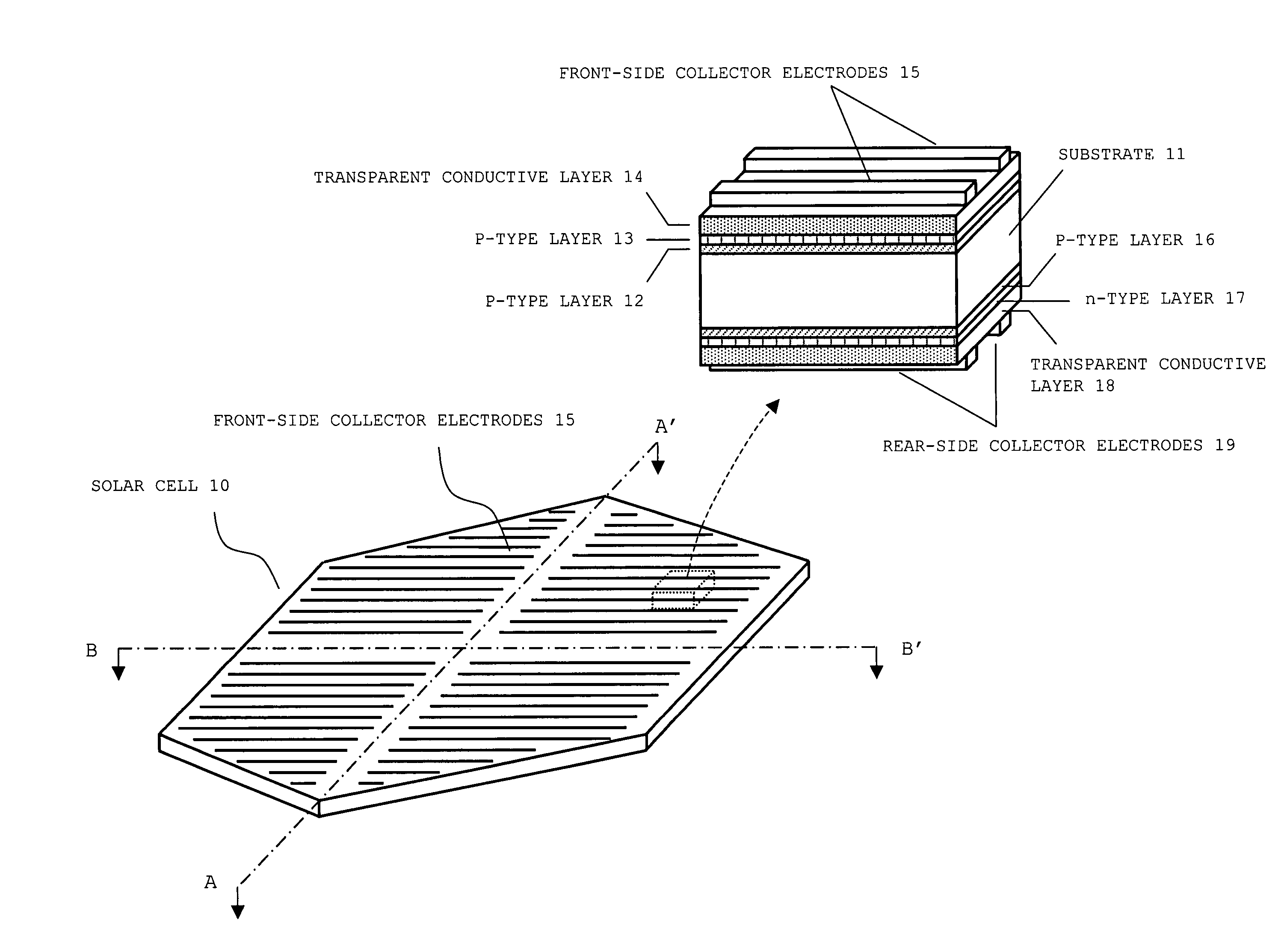
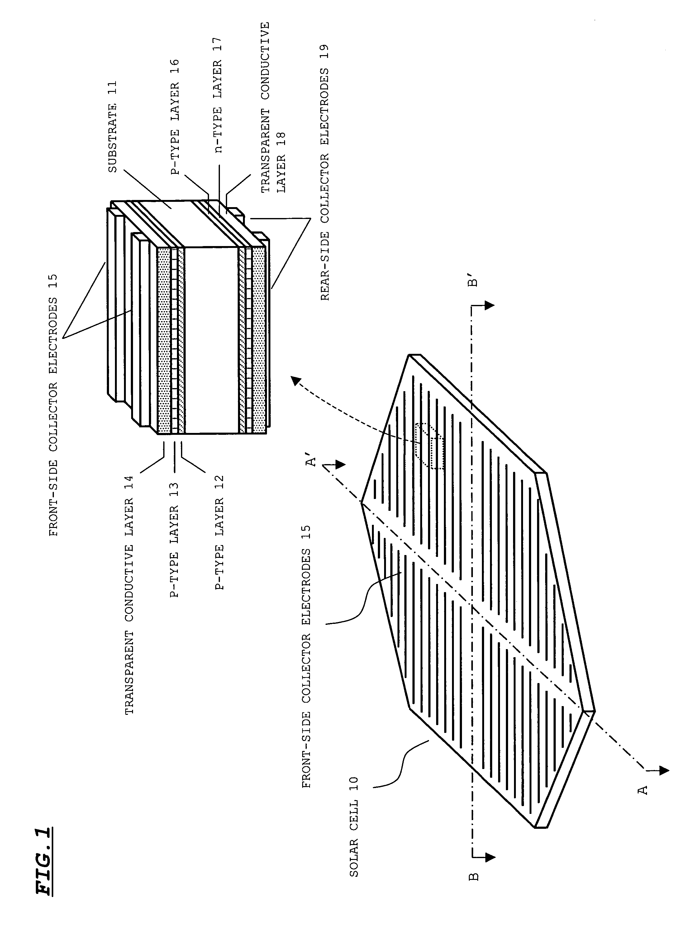
[0066]FIG. 1 illustrates a configuration of a solar cell before being divided into four pieces. As shown in the figure, a solar cell 10 is in a shape of a planer regular hexagon, and collector electrodes 15 and 19 are formed on a front surface and a rear surface, respectively, of the cell. Although not shown in FIG. 1, the solar cell 10 is also provided with electrodes (described later) respectively on the front surface and the rear surface, and these electrodes further collect photovoltaic current collected by the collector electrodes 15 and 19.
[0067]A cross-sectional configuration of the solar cell 10 is shown on the upper right of FIG. 1. As shown in this figure, the solar cell 10 includes a substrate 11, an i-type layer 12, a p-type layer 13, a transparent electrode film 14, the front-side collector electrode 15, an i-type layer 16, an n-type layer 17, a transparent conductive layer 18, and the rear-side collector electrode 19.
[0068]The substrate 11...
configuration example 2
1. Configuration of Solar Cell
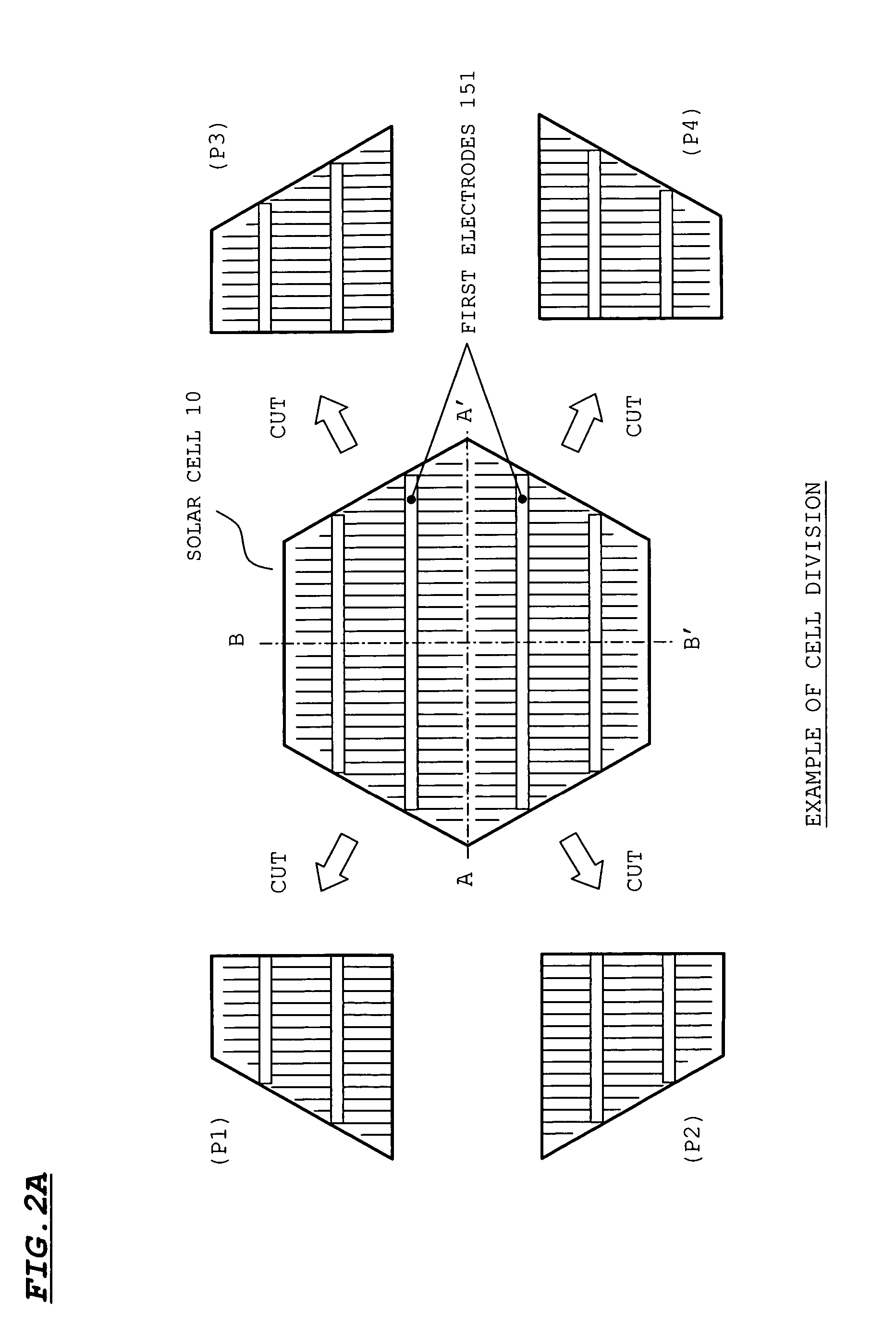
[0087]FIG. 5 illustrates another configuration example of a solar cell and a divided cell. The structure of the layers in this solar cell is the same as the structure shown in FIG. 1, other than the direction of arrangement of the collector electrode 15. According to this configuration example, the front-side collector electrode 15 and the rear-side collector electrode 19 extend in a direction perpendicular to the extension direction in the case of FIG. 1 (A-A′ in FIG. 5). Further, the first electrodes 151 are configured to be electrically connected to the front-side collector electrode 15 and the rear-side collector electrode 19. Although the first electrodes 151 are each configured so as to extend continuously from the one end to the other end of the solar cell 10 in FIG. 5, the first electrodes 151 may be divided at positions corresponding to the line A-A′ into an upper part and a lower part, so that gaps are provided at the positions corresponding t...
PUM
 Abstract
Description
Claims
Application Information