Probe Assembly for Attaching a Chromatography Device to a Mass Spectrometer

a mass spectrometer and assembly technology, applied in the direction of electron multiplier details, particle separator tube details, instruments, etc., can solve the problems of requiring dexterity and skill to assemble, affecting the accuracy of mass spectrometer measurements, and requiring awkward connection that requires dexterity and skill to connect, so as to achieve the effect of cheap production

Active Publication Date: 2016-07-28
MICROMASS UK LTD
View PDF4 Cites 8 Cited by
  • Summary
  • Abstract
  • Description
  • Claims
  • Application Information

AI Technical Summary

Benefits of technology

The invention is a probe assembly for delivering eluent to a mass spectrometer. The joint between the insulated fluid line and the conductive capillary is located downstream of the attachment device that attaches the probe to the spectrometer. This prevents the eluent from leaking out of the spectrometer when the probe is attached, which could be dangerous. A conductive member is included to allow for easy supply of voltage to the conductive capillary from the mass spectrometer through the attachment device. This structure allows for quick and easy connection of the spectrometer to the conductive capillary, resulting in a cost-effective and disposable unit.

Problems solved by technology

However, connecting liquid chromatography systems to mass spectrometers can be a difficult and time consuming task.
This results in an awkward connection that requires dexterity and skill to assemble.
Moreover, there is a risk of electric shock at the connection for the user assembling the instrument connection if there is a leak.
The connecting assembly can also be expensive.
Furthermore, the fitting of the liquid chromatography tube connection into an Electrospray source can take a long time, resulting in inactivity of the instrument.
Poor instrument performance may also occur if parts are omitted or poorly assembled.
This can result in dead volumes, which may lead to poor reproducibility or poor performance of the instrument.

Method used


Image

  • Probe Assembly for Attaching a Chromatography Device to a Mass Spectrometer
  • Probe Assembly for Attaching a Chromatography Device to a Mass Spectrometer
  • Probe Assembly for Attaching a Chromatography Device to a Mass Spectrometer

Examples


Embodiment Construction

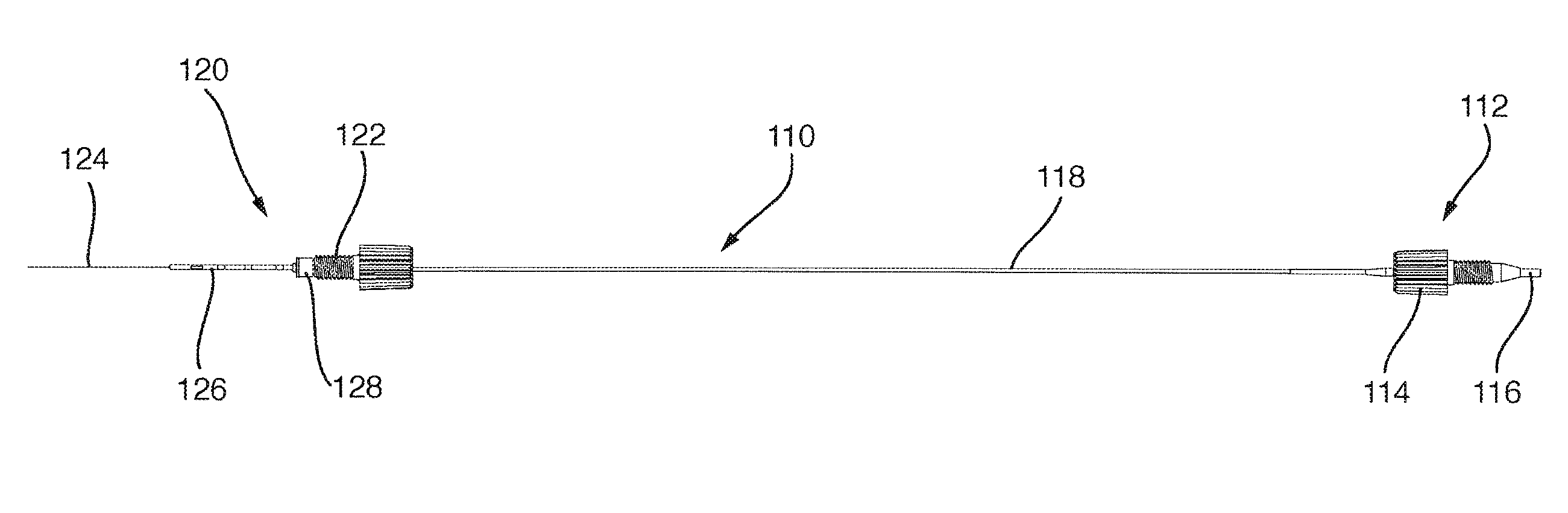
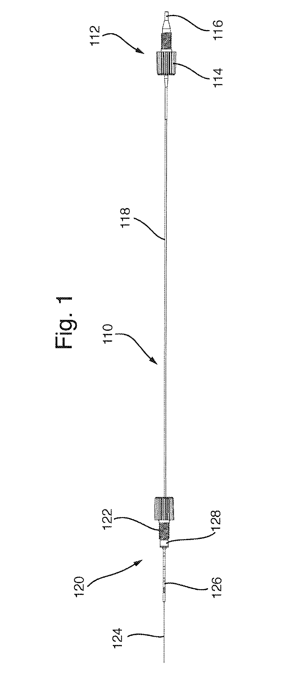
[0148]FIG. 1 shows a probe assembly 110 according to an embodiment of the present invention. The probe assembly 110 has an inlet end 112 having an inlet attachment fitting 114 that is configured for attaching the probe to a liquid chromatography device (not shown). A fluid inlet 116 is located at the inlet end 112 of the probe and is arranged to be insertable into a liquid chromatography output (not shown) such that the fluid inlet 116 receives eluent from the liquid chromatography instrument. An electrically insulating fluid line 118 runs from the fluid inlet 116 to an outlet end 120 of the probe. The inlet end 112 of the probe will be described in more detail in relation to FIG. 4.

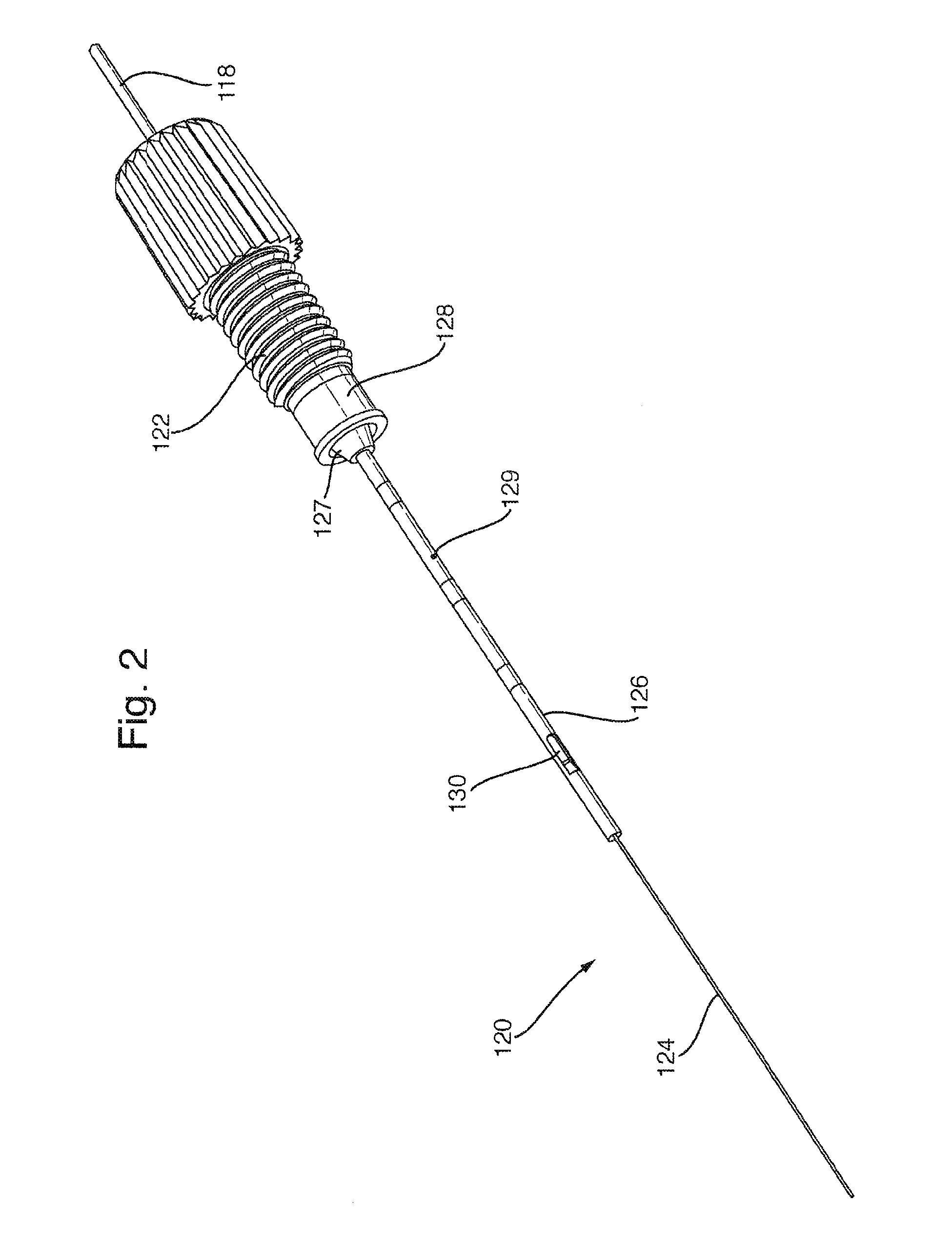
[0149]FIG. 2 shows the outlet end 120 of the probe assembly in more detail. In use, the outlet end 120 is inserted into the ion source of a mass spectrometer (not shown) and is releasably secured in the mass spectrometer by the outlet attachment fitting 122. The attachment fitting comprises a screw threa...


PUM

PropertyMeasurementUnit
voltageaaaaaaaaaa
frequencyaaaaaaaaaa
pressureaaaaaaaaaa

Abstract

A probe assembly is disclosed comprising an inlet for receiving an eluent from a chromatography device; an outlet (120) for delivering the eluent to an ion source of a mass spectrometer; and an attachment device (122) for attaching the outlet to the mass spectrometer. The outlet comprises an electrically conductive capillary (124) and an electrically conductive member (129) surrounding at least part of the electrically conductive capillary (124). The electrically conductive member (129) is arranged to receive a voltage upon connection of the attachment device (122) to the mass spectrometer and the electrically conductive member (129) is arranged to provide an electrical connection from the electrically conductive member (129) to the electrically conductive capillary (124).

Description

CROSS-REFERENCE TO RELATED APPLICATION[0001]This application claims priority from and the benefit of United Kingdom patent application No. 1316890.1 filed on 23 Sep. 2013 and European patent application No. 13185632.0 filed on 23 Sep. 2013. The entire contents of these applications are incorporated herein by reference.BACKGROUND TO THE PRESENT INVENTION[0002]This invention relates generally to probe assemblies for mass spectrometers. The preferred embodiment of this invention relates to atmospheric pressure ionisation probes for use with mass spectrometry systems.[0003]Liquid chromatography systems are an important tool to the analytical chemist for the separation and analysis of samples of interest. Often, after separation in the liquid chromatograph, the components require further analysis to confirm the identity of these components. This is generally best performed using a mass spectrometer. However, connecting liquid chromatography systems to mass spectrometers can be a difficul...

Claims


Application Information

Patent Timeline
Patent Type & Authority Applications(United States)
IPC IPC(8): H01J49/04G01N27/62G01N30/72
CPCH01J49/0404G01N27/622H01J49/0431G01N30/7233G01N30/7266H01J43/24H01J47/005
Inventor O'BRIEN, STEVETRIVETT, IAN
Owner MICROMASS UK LTD
Why Eureka
Try Eureka