Liquid jet head and liquid jet apparatus incorporating same

a liquid jet and apparatus technology, applied in the direction of coatings, printing, special surfaces, etc., can solve the problems of mass productivity decline, manufacturing yield decline, manufacturing difficulty, etc., and achieve the effect of reducing the number of wiring electrodes on the flexible substrate, enhancing the insulation properties of both electrodes, and reducing manufacturing costs

Active Publication Date: 2013-12-03
SII PRINTEK
View PDF5 Cites 8 Cited by
  • Summary
  • Abstract
  • Description
  • Claims
  • Application Information

AI Technical Summary

Benefits of technology

[0011]The present invention has been made in view of the above-mentioned circumstances, and it is therefore an object of the present invention to provide a liquid jet head which can be easily constituted, a liquid jet apparatus, and a method of manufacturing a liquid jet head.
[0025]With this structure, the number of wiring electrodes on the flexible substrate can be reduced substantially by half as compared to the number of extension electrodes on the actuator substrate. In addition, at the intersection at which the wiring electrodes on the flexible substrate intersect, in plan view, the drive electrodes formed on the side surfaces of the partition walls, the clearances are provided between both the electrodes. Accordingly, the insulation properties of both the electrodes can be enhanced. As a result, electric connection between the extension electrodes on the actuator substrate and the wiring electrodes on the flexible substrate is facilitated, thereby enabling increase in manufacturing yields and reduction in manufacturing cost.

Problems solved by technology

As a result, there arises such a problem that the manufacturing becomes difficult or manufacturing yields decrease.
Therefore, there arises such a problem that the manufacturing process becomes complex and accordingly mass productivity decreases.

Method used


Image

  • Liquid jet head and liquid jet apparatus incorporating same
  • Liquid jet head and liquid jet apparatus incorporating same
  • Liquid jet head and liquid jet apparatus incorporating same

Examples


first embodiment

[0042](First Embodiment)

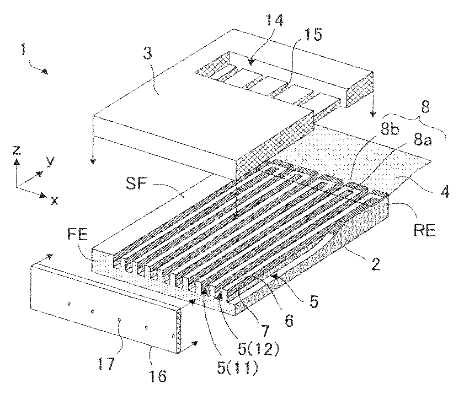
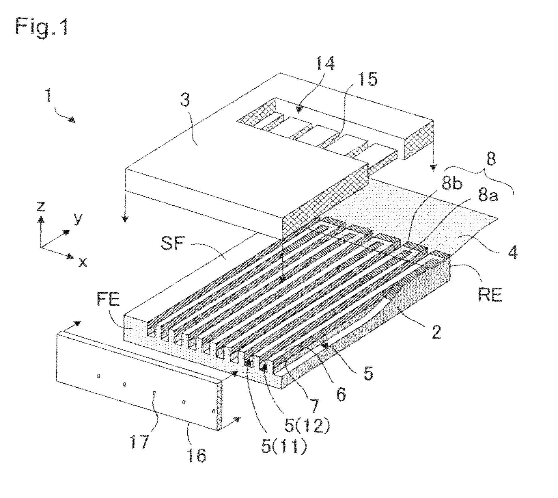
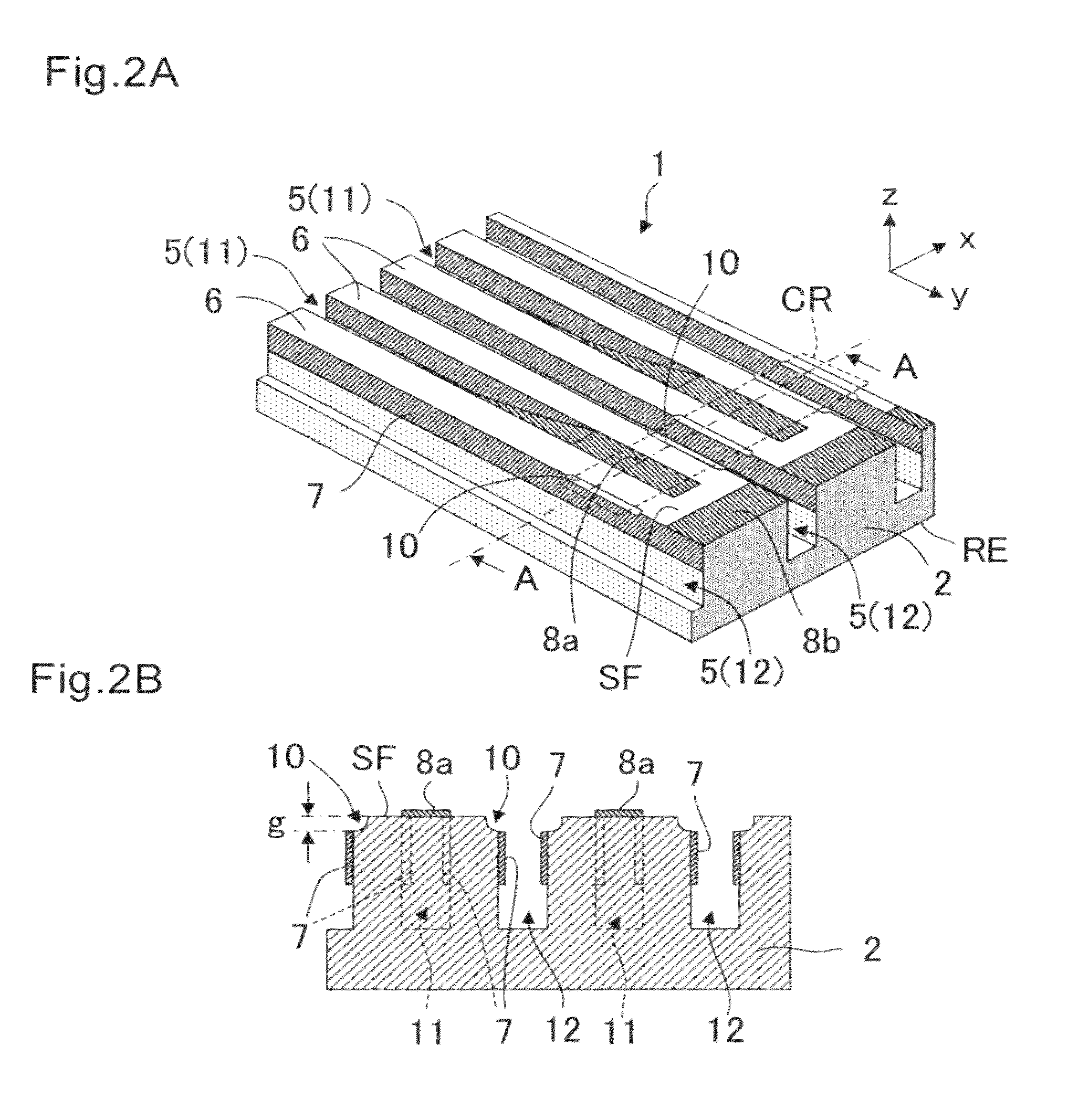
[0043]FIGS. 1 to 3B are explanatory views illustrating a liquid jet head 1 according to a first embodiment of the present invention. FIG. 1 is a schematic exploded perspective view of the liquid jet head 1. FIGS. 2A and 2B are explanatory views of an actuator substrate 2. FIGS. 3A and 3B are views illustrating a state in which a flexible substrate 4 is bonded to the actuator substrate 2.

[0044]As illustrated in FIG. 1, the liquid jet head 1 includes the actuator substrate 2, a cover plate 3, the flexible substrate 4, and a nozzle plate 16. The actuator substrate 2 includes: a plurality of grooves 5, which are elongated in a “y” direction, that is, a direction from a front end FE of a substrate surface SF to a rear end RE thereof, and arranged in an “x” direction intersecting the above-mentioned “y” direction while being spaced apart from one another through an intermediation of partition walls 6; drive electrodes 7, which are formed on side surfaces of each of...

second embodiment

[0053](Second Embodiment)

[0054]FIG. 4 is a schematic partial perspective view illustrating an actuator substrate 2 of a liquid jet head 1 on a rear end RE side according to a second embodiment of the present invention. The second embodiment is different from the first embodiment in that the grooves 5 constituting the discharge channels 11 extend to the rear end RE, and the common extension electrode 8a and the individual extension electrode 8b corresponding to one discharge channel 11 are separated on the upper surfaces of the two partition walls 6 situated on both the sides of the discharge channel 11.

[0055]The liquid jet head 1 includes the actuator substrate 2, a cover plate (not shown) bonded onto the actuator substrate 2, a flexible substrate 4 (see FIG. 5) bonded to the substrate surface of the actuator substrate 2 in the vicinity of the rear end RE, and a nozzle plate (not shown) bonded to the actuator substrate 2 and the cover plate at a front end FE thereof. The structures ...

third embodiment

[0075](Third Embodiment)

[0076]FIGS. 9A to 9F and FIGS. 10A to 10D are schematic cross-sectional views of a liquid jet head 1 for describing a method of manufacturing the liquid jet head 1 according to a third embodiment of the present invention. The same components or components having the same function are represented by the same reference symbols.

[0077]FIGS. 9A and 9B illustrate a substrate preparing step. The actuator substrate 2 formed of a piezoelectric substrate is prepared. A PZT ceramic material subjected to polarization processing in a direction perpendicular to the substrate surface is used as the piezoelectric substrate. FIG. 9B illustrates a state in which a photosensitive resin 21 is applied to the substrate surface of the actuator substrate 2 and is patterned. For example, the photosensitive resin 21 is patterned so that the photosensitive resin 21 is removed in a region in which the extension electrodes are to be formed, and the photosensitive resin 21 is left in a re...


PUM


Abstract

A liquid jet head includes an actuator substrate having grooves, and a flexible substrate for supplying a drive signal to the actuator substrate. On a surface of the actuator substrate, in the vicinity of a rear end thereof, are formed a common extension electrode and an individual extension electrode connected to drive electrodes of a discharge channel and dummy channels, respectively. The common extension electrode and the individual extension electrode are connected to a common wiring electrode and an individual wiring electrode of the flexible substrate, respectively. In a common wiring intersection region in which the common wiring electrode of the flexible substrate intersects the drive electrodes of the actuator substrate, upper end portions of the drive electrodes on side surfaces of the dummy channels are formed deeper than the substrate surface.

Description

BACKGROUND OF THE INVENTION[0001]1. Field of the Invention[0002]The present invention relates to a liquid jet head for discharging liquid from nozzles to form images and characters on a recording medium or form a thin film material, and also relates to a liquid jet apparatus using the liquid jet head.[0003]2. Description of the Related Art[0004]In recent years, an ink jet system liquid jet head has been used for creating characters and graphics by discharging ink droplets onto a recording sheet or the like, or forming a pattern of a functional thin film by discharging a liquid material onto a surface of an element substrate. In the ink jet system, ink or a liquid material is supplied from a liquid tank to the liquid jet head through a supply tube, and the ink is loaded into small spaces formed in the liquid jet head. In response to a drive signal, the volume of the small spaces is instantaneously reduced to discharge liquid droplets from nozzles communicating to grooves.[0005]FIG. 1...

Claims


Application Information

Patent Timeline
Patent Type & Authority Patents(United States)
IPC IPC(8): B41J2/135
CPCB41J2/14209B41J2002/14491B41J2/16B41J2/045B41J2/055
Inventor KOSEKI, OSAMU
Owner SII PRINTEK
Why Eureka
Try Eureka