Dust clearing blow-back valve and reservoir

a blow-back valve and reservoir technology, applied in the field of processing and conveyance, can solve the problems of clogging the filter, affecting the suction level of the vacuum source, and the container is usually too heavy to be lifted manually, and achieves the effect of rapid opening of the valve stem

Active Publication Date: 2011-12-06
MAGUIRE STEPHEN B
View PDF71 Cites 32 Cited by
  • Summary
  • Abstract
  • Description
  • Claims
  • Application Information

AI Technical Summary

Benefits of technology

[0019]In operation, the valve stem is actuated by movement of the diaphragm. Pilot air is supplied to the pilot air chamber by from a source of plant air at low pressure, with pilot air flow into the pilot air chamber controlled by a solenoid actuated valve. The influx of pilot air into the pilot air chamber causes flexing of the diaphragm away from the pilot air chamber, leading to movement and a rapid opening of the valve stem. This actuation of the valve stem opens the passageway connecting the exhaust conduit and the high pressure accumulator chamber so the pressurized gas (which is typically air), within the high pressure accumulator effectively immediately passes through the exhaust conduit and into a line, connected to the vacuum source, in which the filter is located. The pressurized gas is thereby directed by the conduit towards the air filter in the line leading to the vacuum source, in a direction opposite that of the normal flow of air therein, thereby largely if not entirely blowing dust and undesired particles off the filter.

Problems solved by technology

The containers are usually too heavy to be lifted manually.
When the vacuum drawing stops, however, the dust and contaminants remain, clogging the filter.
It also compromises the level of suction furnished by the vacuum source.
Without such an accumulator, the volume and pressure of air available to blow dust off the filter in the vacuum loader is limited by the amount of air that can flow through the pilot air supply line.
The resulting improvement however, has several limitations.
This is because flow of air into the vacuum loader chamber, where the filter to be cleaned is located, is limited by the size, namely the cross-sectional area, of the internal orifice of the actuating solenoid, through which the “cleaning blast air” must pass.
Even when using an accumulator having an associated reservoir, the resulting air blast is limited by the cross-sectional area of the passageway through the solenoid valve, thereby only clearing a correspondingly sized area on the filter; the remainder of the filter is not cleaned.
While simply providing a larger solenoid valve is a possible solution, there are significant cost increases associated with larger solenoid valves.
Costs associated with providing a solenoid valve large enough to cover the entire filter is prohibitive.
Even with this approach, there is still reduced effectiveness of the vacuum source due to the remaining clogged portions of the filter, when a solenoid valve having a passageway with a cross-sectional area less than the area of the filter is used.
However, this does little to improve the situation.
The available “plant” air flow in modern plastic resin processing facilities is simply too limited to provide sufficient volume and pressure for a multi-outlet configuration to function effectively.

Method used


Image

  • Dust clearing blow-back valve and reservoir
  • Dust clearing blow-back valve and reservoir
  • Dust clearing blow-back valve and reservoir

Examples


Embodiment Construction

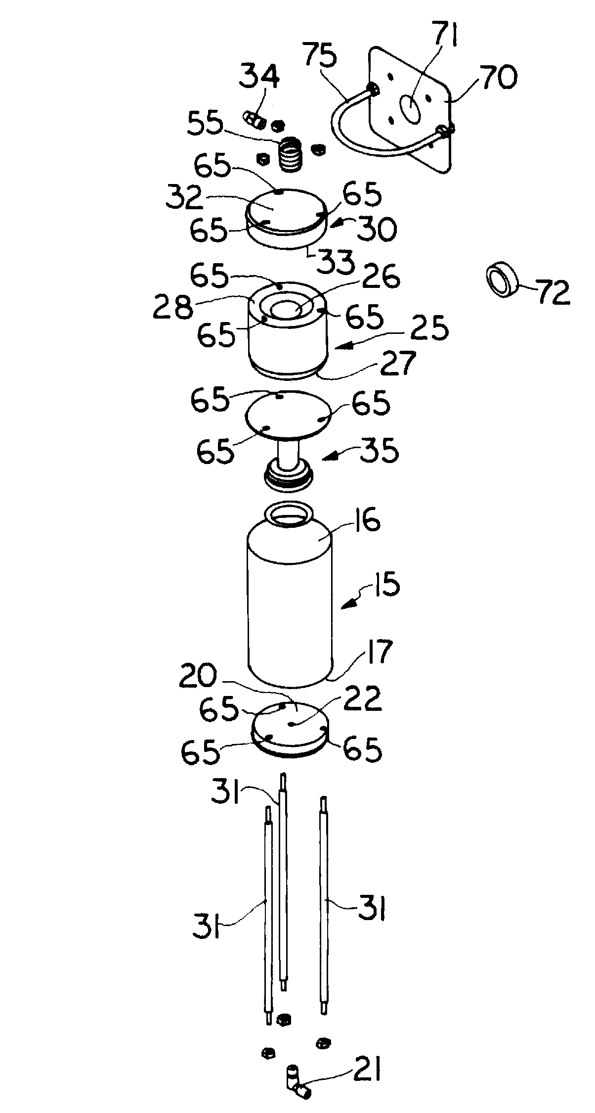
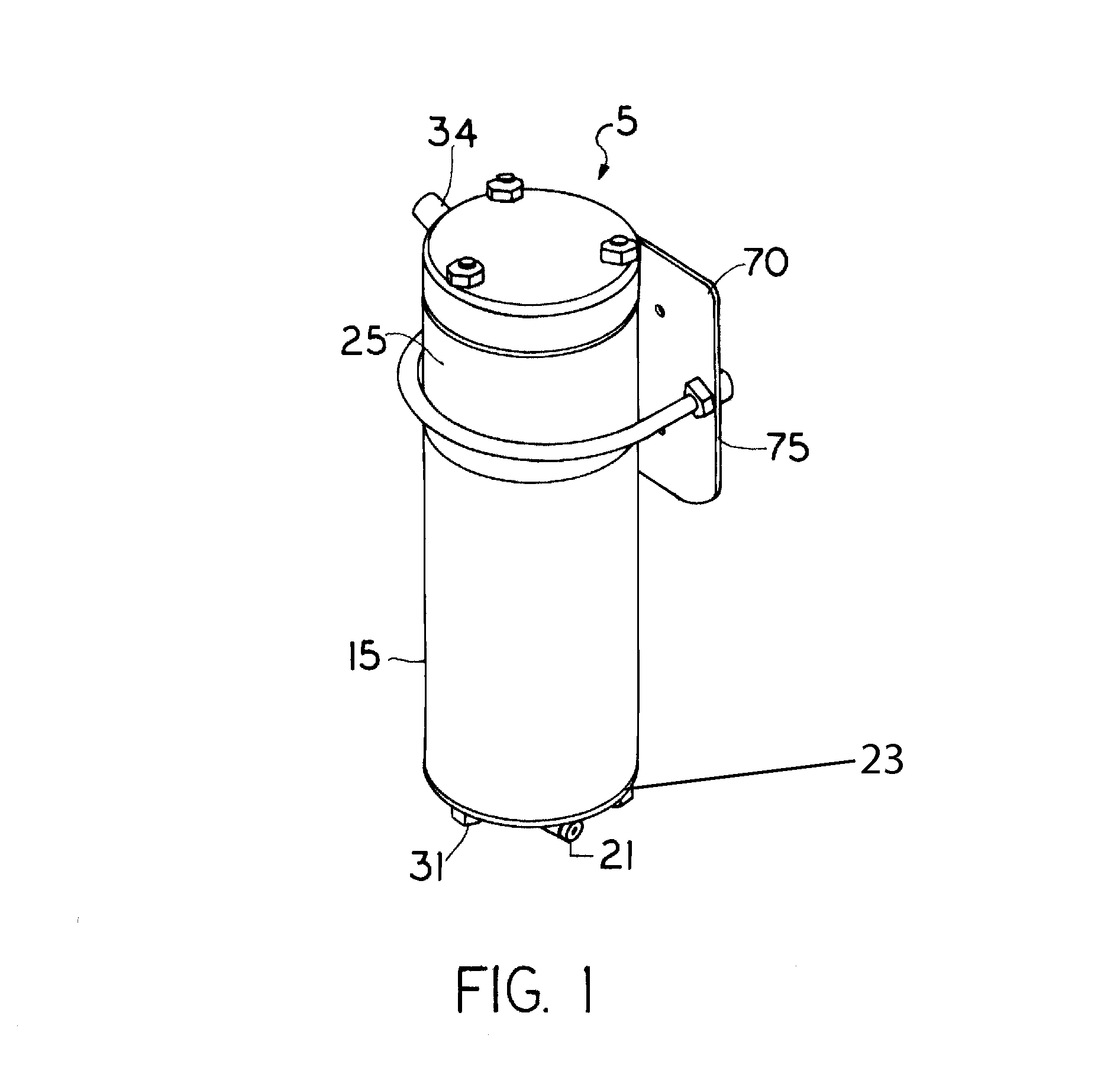
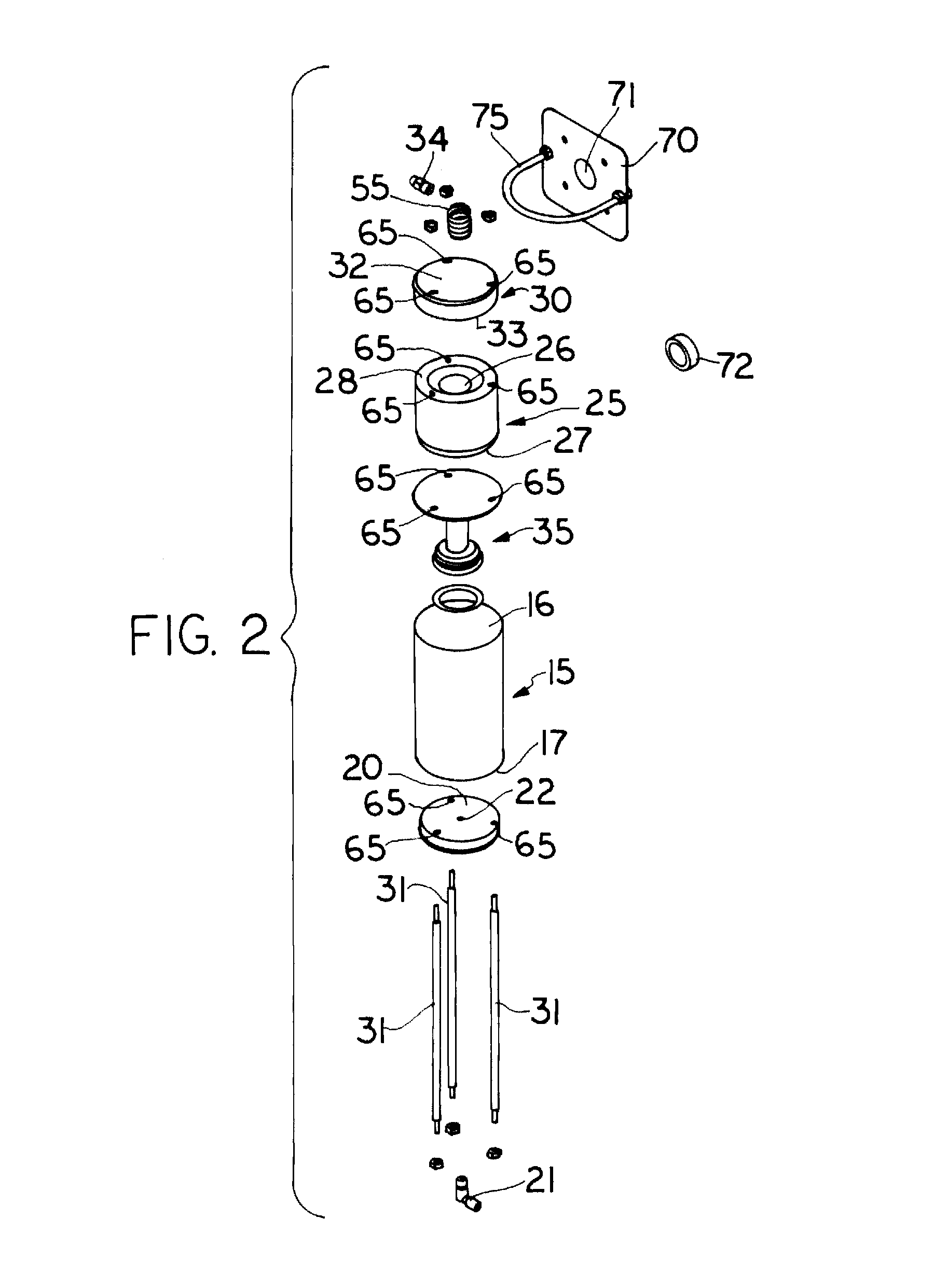
[0032]This invention relates to processing and conveyance of granular resin pellets and other powdery materials, which materials during or after conveyance must be filtered prior to use. More specifically, this invention relates to apparatus and methods of providing compressed air to an air filter of a vacuum powered and vacuum conveying resin transport device wherein compressed air is applied to the filter, in a direction opposite that through which air is drawn by the vacuum, to clear the filter of unwanted particles. The invention provides a filter “blowback” device providing a blast of compressed air, in a reverse direction through a filter to clear the filter of dust.

[0033]Referring to FIGS. 1 through 7, a vacuum loader manufacturing aspects of the invention is illustrated with a blowback assembly designated generally 5 and a vacuum source designated generally 10. InFIGS. 1 through 4, the blowback assembly 5 of the invention is illustrated in greater detail. As illustrated in ...


PUM

PropertyMeasurementUnit
diameteraaaaaaaaaa
diameteraaaaaaaaaa
pressureaaaaaaaaaa

Abstract

An accumulator having an internal valve opened by applying air pressure to a diaphragm with a small solenoid to apply air to the diaphragm where the air is supplied from a pilot air supply. When the internal valve operated by the diaphragm opens, it snaps to a fully open position thereby opening the valve and uncovering a passageway leading to a filter for cleaning. The passageway is sufficiently wide that the resulting flow of air through the passageway is so explosive that air pressure on the filter is distributed over the surface area of the filter for a brief moment, blowing the dust on the filter free.

Description

CROSS REFERENCE TO RELATED PATENT APPLICATION[0001]This patent application is based on and claims the priority of U.S. provisional patent application Ser. No. 60 / 967,065 filed 31 Aug. 2007 in the name of Stephen B. Maguire for an invention entitled “Diaphragm Actuated Blow-Back Valve and Reservoir”; the priority is claimed under the applicable provisions of 35 USC 119 and 35 USC 120. The disclosure of U.S. provisional patent application 60 / 967,065 is hereby incorporated by reference in its entirety.FIELD OF INVENTION[0002]This invention relates to processing and conveyance of granular resin pellets and other powdery materials that must be filtered prior to use. More specifically, this invention relates to apparatus and methods of providing compressed air to a filter of a resin conveying device powered by vacuum, wherein the compressed air is applied in a direction opposite to that of the vacuum draw to clear the filter of dust and other unwanted particulate matter.BACKGROUND OF THE ...

Claims


Application Information

Patent Timeline
Patent Type & Authority Patents(United States)
IPC IPC(8): B01D46/04
CPCB01D46/0068Y10T137/86928Y10T137/3021B01D46/71
Inventor MAGUIRE, STEPHEN B.
Owner MAGUIRE STEPHEN B
Why Eureka
Try Eureka