Antenna structure

a technology of antenna structure and antenna, applied in the direction of resonant antenna, elongated active element feed, protective material radiating elements, etc., can solve the problem that the built-in antenna cannot be rotated to face a direction, the traditional antenna has a following, and it takes more time and movements to adjust the position and the direction of the exterior antenna

Inactive Publication Date: 2011-12-06
LITE ON TECH CORP +1
View PDF4 Cites 0 Cited by
  • Summary
  • Abstract
  • Description
  • Claims
  • Application Information

AI Technical Summary

Benefits of technology

[0013]The antenna structure is applied for a communication system. For example, the wireless router system includes a wireless router station and the antenna structure of the present invention. The wireless router system can be applied for connecting with desktop computer or laptop computer so that the computers can connect to the internet. Users can know the signal quality shown on the displaying monitor so that user can adjust the position or angle of the antenna structure for obtaining better transmission signals. In other words, when the wireless signal is not good, user can rotate the antenna structure or bend the antenna structure in various directions vertical to the axial direction of the antenna structure. Therefore, the position or the direction of the antenna structure can be adjusted for improving the signal quality so that user can connect internet more stable. At least one bendable piece is provided in the antenna structure for replacing the rotating shaft of the traditional antenna. Therefore, the problem that the rotating shaft only can be bent in one direction is solved. In other words, the antenna structure can be bent in various directions so as to improve the signal transmission.
[0014]Furthermore, the components of the traditional antenna structure are simplified. In other words, the assembly of the antenna structure of the present invention is optimized so that the size and the volume of the antenna structure of the present invention are reduced. The bendable piece and the signal emitting / receiving portion are covered by the sheath so that the components are not exposed. Furthermore, the manufacturing process of the antenna structure is optimized. The bendable piece is provided into the mold and the antenna structure can be formed in one procedure so that the manufacturing processes are simplified and the manufacturing cost is reduced.
[0016]The sheath has a concave portion corresponding to the bendable piece so that user can bend the antenna structure. User can hold the concave portion so as to bend the bendable piece. Therefore, the concave portion performs as an operation space so that it's convenient for users to bend the antenna structure.
[0017]The concave portion has anti-slide structure thereon, for example, a concave-convex continuous anti-slide pattern, for noticing the bending position for users. Furthermore, the anti-slide structure is used for preventing the hand of the user from sliding when the user is forcing on the bendable piece.

Problems solved by technology

However, the built-in antenna cannot be rotated to face a direction which is aligning the direction of the signals.
However, the traditional antenna has following disadvantage.
Therefore, it costs more time and movements to adjust the position and the direction of the exterior antenna 11′.

Method used


Image

  • Antenna structure
  • Antenna structure
  • Antenna structure

Examples


Embodiment Construction

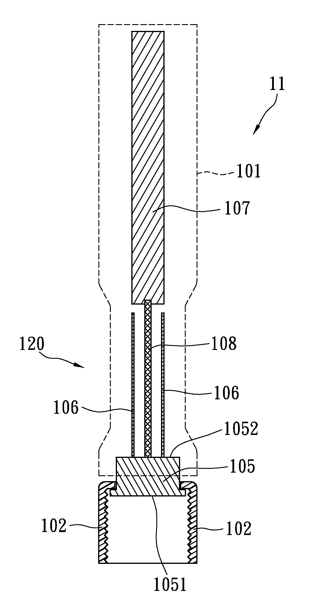
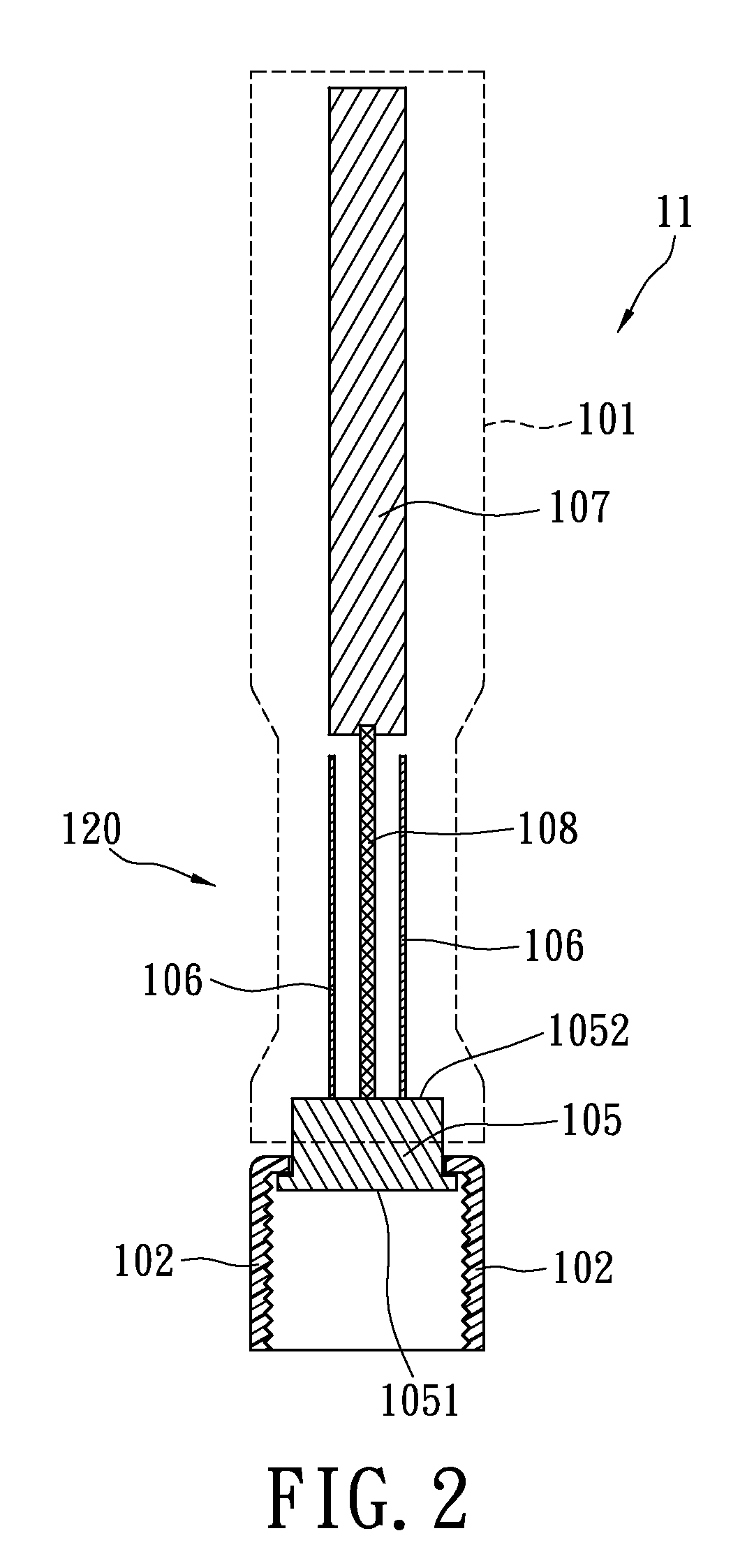
[0025]Reference is made to FIGS. 2 and 3. The present invention provides an antenna structure 11 which can be applied to a communication system, such as a wireless router (not shown). The router is a networking device and can be used for applying for networking signals so that computers covered in the signals can have connectivity for internet. The wireless router can use for encoding the received signals and emitting the transformed internet signals so that the internet signal coverage is formed.

[0026]The antenna structure 11 has an assembling portion 102 which can be used for fixing the antenna structure 11 on the router. Please refer to FIG. 2; the assembling portion 102 has screw threads so that the assembling portion 102 can be fixed on the router by a screwing manner. Preferably, the antenna structure 11 has standard screw threads for connecting to the router, therefore the antenna structure 11 has capability for assembling on other networking devices without re-designing. In ...


PUM


Abstract

The antenna structure is applied for a communication system. The antenna structure has a signal emitting / receiving portion, a flex transmitting line disposed under the signal emitting / receiving portion and electrically connected to the signal emitting / receiving portion, and a connecting portion having a first end and a second end. The first end of the connecting portion is electrically connected to the flex transmitting line, and the second end of the connecting portion is connected to an assembling portion. The antenna structure further includes a bendable piece corresponding to the flex transmitting line. The bendable piece can be bent by a force to change positions, directions, or positions and directions of the signal emitting / receiving portion connected with the flex transmitting line. The bendable piece, the flex transmitting line and the signal emitting / receiving portion are covered by a sheath.

Description

BACKGROUND OF THE INVENTION[0001]1. Field of the Invention[0002]The present invention relates to an antenna structure. In particular, the present invention relates to an exterior antenna structure which can be bent.[0003]2. Description of Related Art[0004]Antenna is widely used for improving the signal emitting / receiving in wireless communication system. Antennas can be classified into two categories which include micro built-in antenna and exterior antenna. The advantages of the built-in antenna include smaller size of the antenna and protection of the antenna. However, the built-in antenna cannot be rotated to face a direction which is aligning the direction of the signals. On the contrary, the exterior antenna can be rotated to adjust its position and direction to obtain stable signals. Therefore, the exterior antenna is more used in the wireless communication system.[0005]Please refer to FIG. 1; the exterior antenna 11′ of the wireless router has an antenna pole 12′. The antenna...

Claims


Application Information

Patent Timeline
Patent Type & Authority Patents(United States)
IPC IPC(8): H01Q1/42
CPCH01Q1/40H01Q1/42H01Q9/16H01Q9/30
Inventor GUO, YAN-LIANGCHEN, CHING-HUILIU, CHIA-YUAN
Owner LITE ON TECH CORP
Why Eureka
Try Eureka