Modular electrical bus system with built in ground circuit

a ground circuit and module technology, applied in the direction of switchgear arrangements, mechanical equipment, transportation and packaging, etc., can solve the problems of not having the required electrical conductivity, limited use of grounding systems made of electrically conductive materials,

Active Publication Date: 2011-12-13
ASCO LP
View PDF32 Cites 23 Cited by
  • Summary
  • Abstract
  • Description
  • Claims
  • Application Information

AI Technical Summary

Problems solved by technology

However, this type of grounding system limited the use of housings made from electrically conductive materials.
Light weight but structurally sound materials such as plastic or fiberglass are desired to replace the metal material but may not have the needed electrical conductivity required.

Method used


Image

  • Modular electrical bus system with built in ground circuit
  • Modular electrical bus system with built in ground circuit
  • Modular electrical bus system with built in ground circuit

Examples


Embodiment Construction

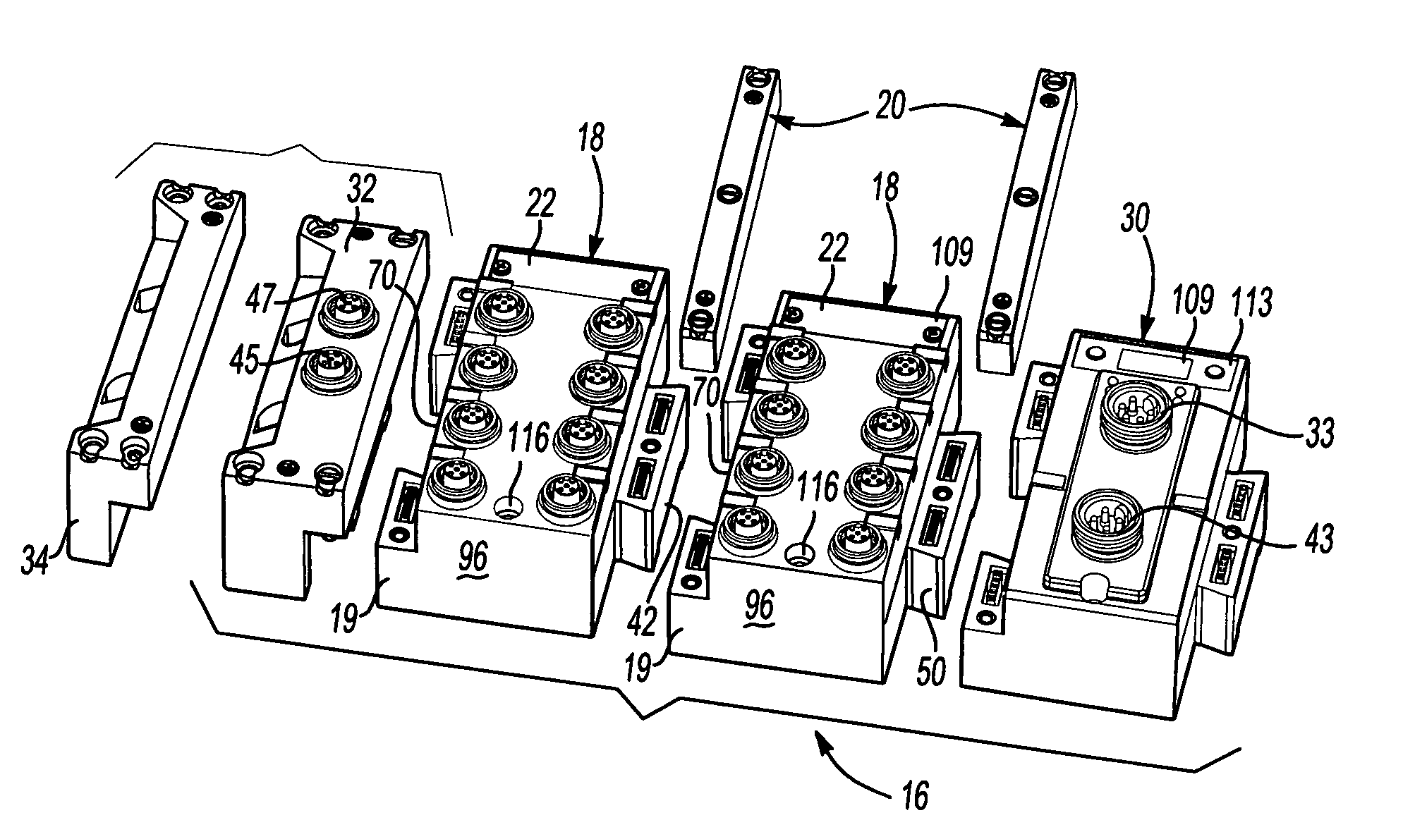
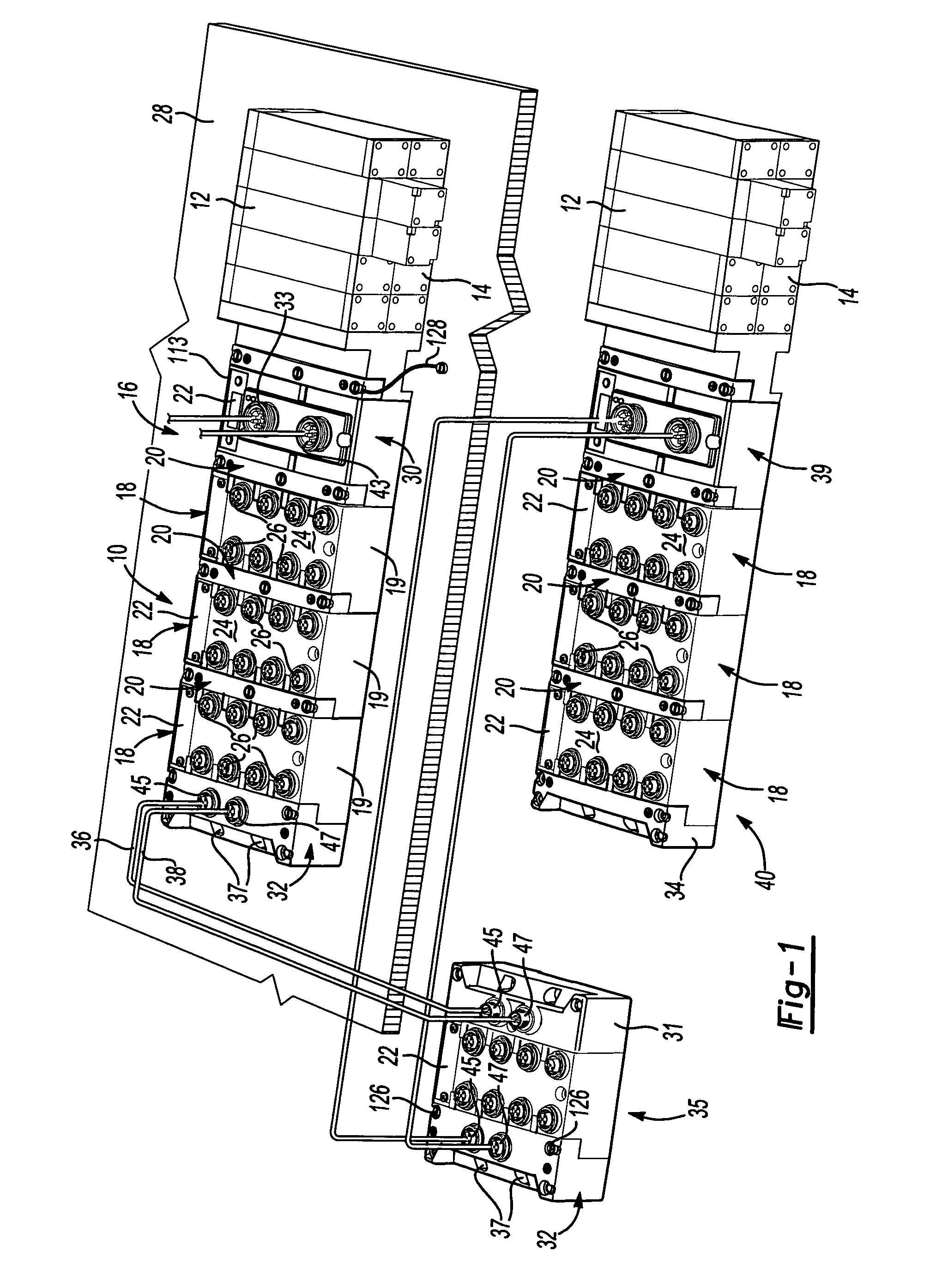
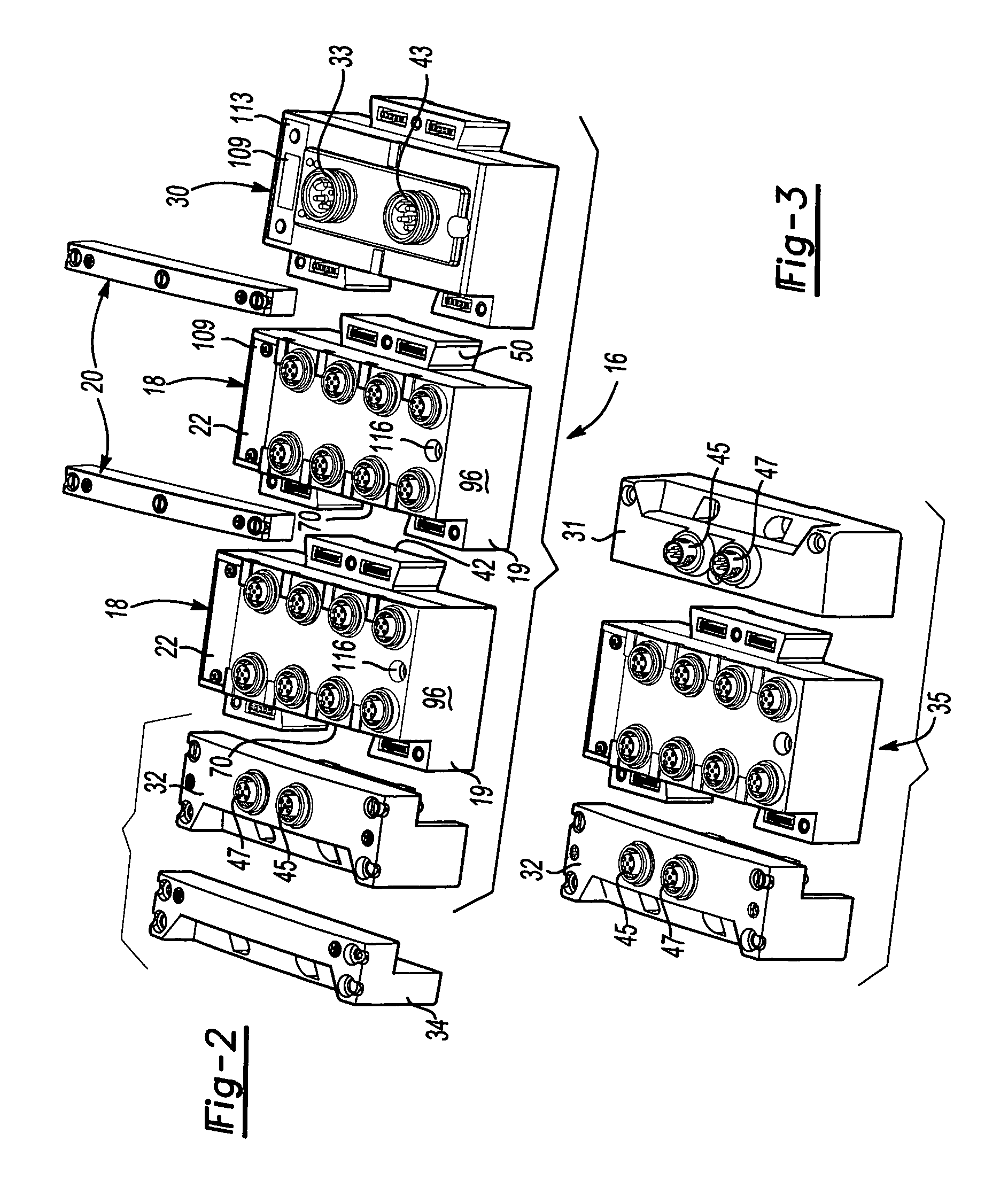
[0034]Referring now to FIG. 1, one arrangement of a modular fieldbus system 10 provides control for solenoid actuated valves 12 which controls directional flow in a valve manifold 14 in a main station 16. The main station 16 has main communication module 30 with an alpha-numeric display 22 mounted thereon. The fieldbus system can also have a plurality of I / O modules 18 connected together via bridge members, which are hereinafter referred to as clips 20 that bridge over and connect two adjacent modules 18 and physically and electrically connect together to the main communication module 30. The main communication module 30 connects to and controls the solenoid valves 12. For purposes of this invention, a module may be modular to be connected with other units or may be a stand alone unit.

[0035]The I / O modules 18 may be banked and mounted on a mounting surface 28 such as a machine wall or panel through an available DIN RAIL system or directly fastened to the mounting surface 28. At one ...


PUM


Abstract

A modular electrical bus system has a grounding circuit through a plurality of modular I / O units with each unit being both electrically and mechanically connectable together via a bridge member connecting adjacent units and the main communication module. The bridge member and modular I / O units are grounded together with a ground circuit that extends within both components.

Description

TECHNICAL FIELD[0001]The field of this invention relates to electrical bus systems that can be used with pneumatic valve manifolds and more particularly a ground system for an electrical bus system.BACKGROUND OF THE DISCLOSURE[0002]Industrial automation uses many control devices. One useful control device combines a plurality of electrical actuated solenoids that control through valves the direction of hydraulic or pneumatic flow for actuating other downstream devices. In recent times these valves have been controlled by field busses which are often mounted adjacent the valve manifold.[0003]Efforts have been made to modularize the field bus with modular input-output modules (I / O) so additional I / O components can be more easily added on or replaced. Each input / output module has a plurality of fittings which can all be used as input fittings, output fittings, or a mix of input and output fittings. This modularity is desirable to remotely place certain I / O modules closer to a particula...

Claims


Application Information

Patent Timeline
Patent Type & Authority Patents(United States)
IPC IPC(8): F15B21/08H01R9/22
CPCF15B13/0857H01R9/2483F15B13/0867Y10T137/8376
Inventor DE CAROLIS, ENRICOESKEW, JOHN F.HUNDT, MICHAEL W.WELKER, JEFFREY
Owner ASCO LP
Why Eureka
Try Eureka