
Rebalancing of audio

a rebalancing and audio technology, applied in the field of digital signal processing, can solve the problems of reducing the overall signal to noise ratio, large increase in loudness, and lifting the noise floor

Active Publication Date: 2011-12-27
TEXAS INSTR INC
View PDF6 Cites 0 Cited by
  • Summary
  • Abstract
  • Description
  • Claims
  • Application Information

AI Technical Summary

Problems solved by technology

If one channel has a very low level, it might require a large increase in loudness, which can lift the noise floor and reduce the overall signal to noise ratio.
These are problems for known balancing methods.

Method used


Image

  • Rebalancing of audio
  • Rebalancing of audio
  • Rebalancing of audio

Examples


Embodiment Construction

1. Overview

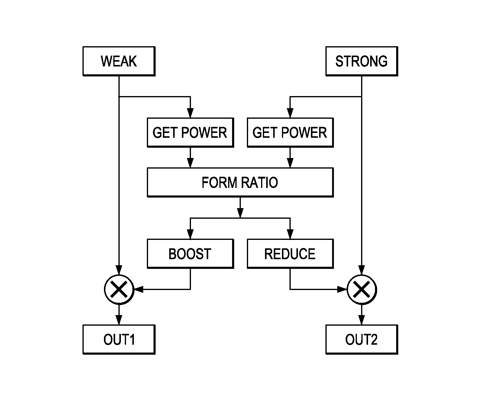
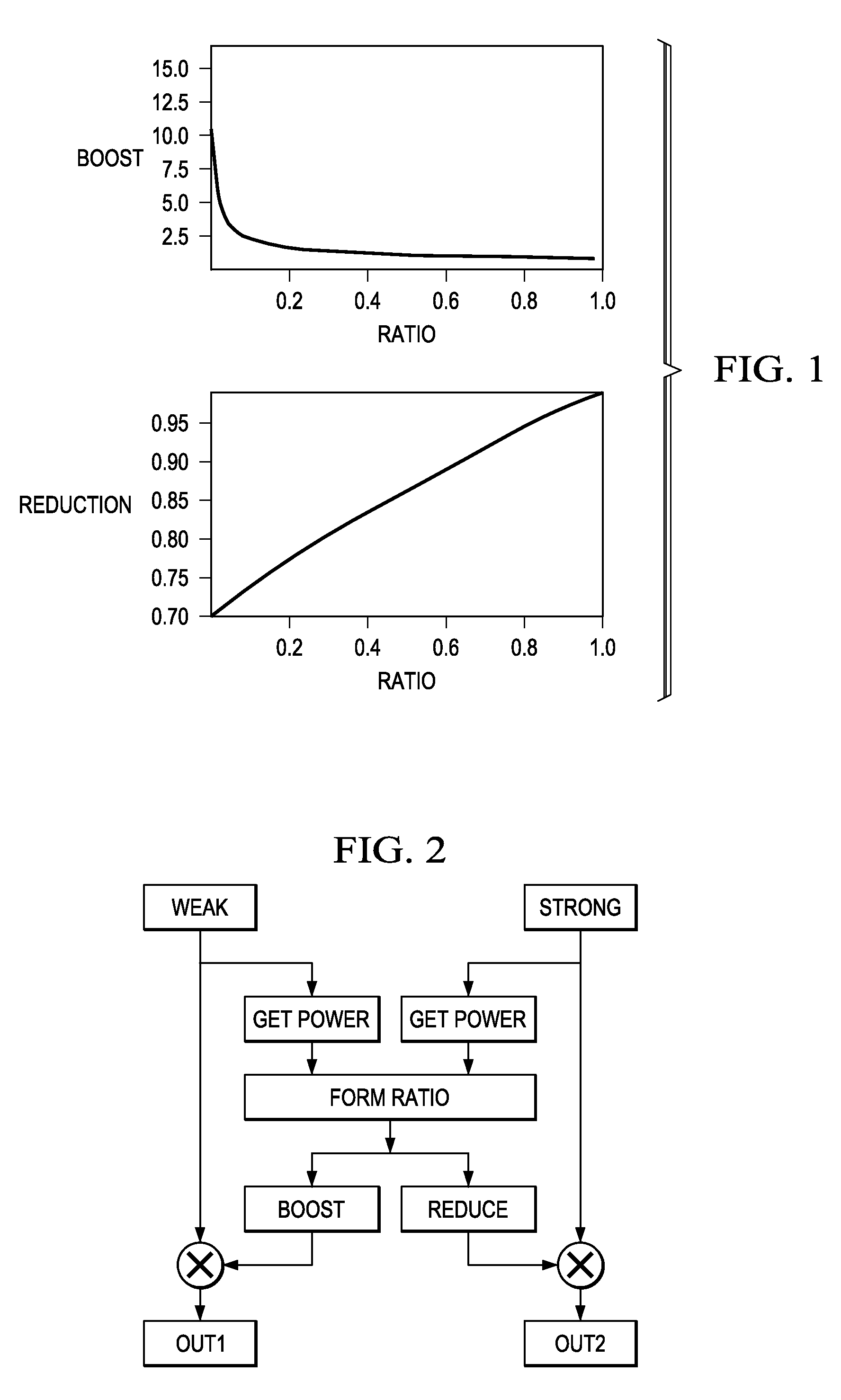
[0015]Preferred embodiment two-channel audio balancing methods include using one input channel to derive both output channels when the other input channel has a very weak or no signal. Also, preferred embodiment methods can balance multi-channel systems where one or more channels have very weak or no input signal by sharing the stronger channel signals to derive output signals for the weak / no-input channels.

[0016]Preferred embodiment application systems (e.g., cellphones, PDAs, portable audio players, etc.) perform preferred embodiment methods with any of several types of hardware: digital signal processors (DSPs), general purpose programmable processors, application specific circuits, or systems on a chip (SoC) such as combinations of a DSP and a RISC processor together with various specialized programmable accelerators. FIG. 9 is an example of an audio-visual processor. A stored program in an onboard or external (flash EEP)ROM or FRAM could implement the signal processi...


PUM


Abstract

Rebalancing of an audio signal refers to achieving a balance of perceived loudness, typically of right and left channels, given an unbalanced input. A flexible method to automatically rebalance an audio input signal is robust against noise in extreme cases through the individual channels combined in various ways as a function of the loudness ratio between input channels.

Description

CROSS-REFERENCE TO RELATED APPLICATIONS[0001]This application claims priority from provisional application No. 60 / 969,033, filed Aug. 30, 2007. The following co-assigned, patent applications disclose related subject matter: application Ser. No. 11 / 560,387, filed Nov. 16, 2006.BACKGROUND OF THE INVENTION[0002]The present invention relates to digital signal processing, and more particularly to multi-channel audio output.[0003]Balance in audio often refers to the ratio of loudness between two signals, typically right and left stereo channels. For instance many stereo hardware components have a knob labeled “balance” to control the loudness ratio of the two speakers. Automatic rebalancing refers to the automatic adjustment of an input signal to achieve nearly equal loudness levels at the outputs. This is useful in the case of, for instance, listening to poorly recorded or poorly mixed music, as is sometimes the case for old LPs, tapes and even CDs.[0004]The basic goal of achieving balan...

Claims


Application Information

Patent Timeline
Patent Type & Authority Patents(United States)
IPC IPC(8): H04R5/00
CPCH04R5/04
Inventor TRAUTMANN, STEVEN DAVIDSAKURAI, ATSUHIROTSUTSUI, RYO
Owner TEXAS INSTR INC
Learn More