Wire stripper

a wire stripper and wire strip technology, applied in the field of wire strippers, can solve the problems of restricted environment space in which the convention wire stripper can be used, and achieve the effect of convenient operation and good ability to strip off wires

Active Publication Date: 2012-01-10
KAUW YEHI IND CO LTD
View PDF6 Cites 2 Cited by
  • Summary
  • Abstract
  • Description
  • Claims
  • Application Information

AI Technical Summary

Benefits of technology

[0006]The objective of the present invention is to provide a wire stripper, which has a good capability of stripping off a wire, and can be operated easily without being restricted by the environmental space.
[0010]In the wire stripper of the present invention, the first rails, the second rails and the acting portion provide a good acting mechanism, whereby the action of stripping off the wire can be operated smoothly with a proper magnitude of force. Thus, the insulating surface of the wire can be stripped off easily, and the integrity of leads within the wire can be protected. The elastic force of the spring portion allows the upper engaging portion to be separated from the lower engaging portion after their engagement, thereby preventing the naked leads from suffering damage. Further, the upper engaging portion and the lower engaging portion can be put into a narrow space to strip off the wire, so that the present invention will not be restricted by an environmental space.

Problems solved by technology

Thus, the environmental space in which the convention wire stripper can be used is restricted.

Method used


Image

  • Wire stripper
  • Wire stripper
  • Wire stripper

Examples


Embodiment Construction

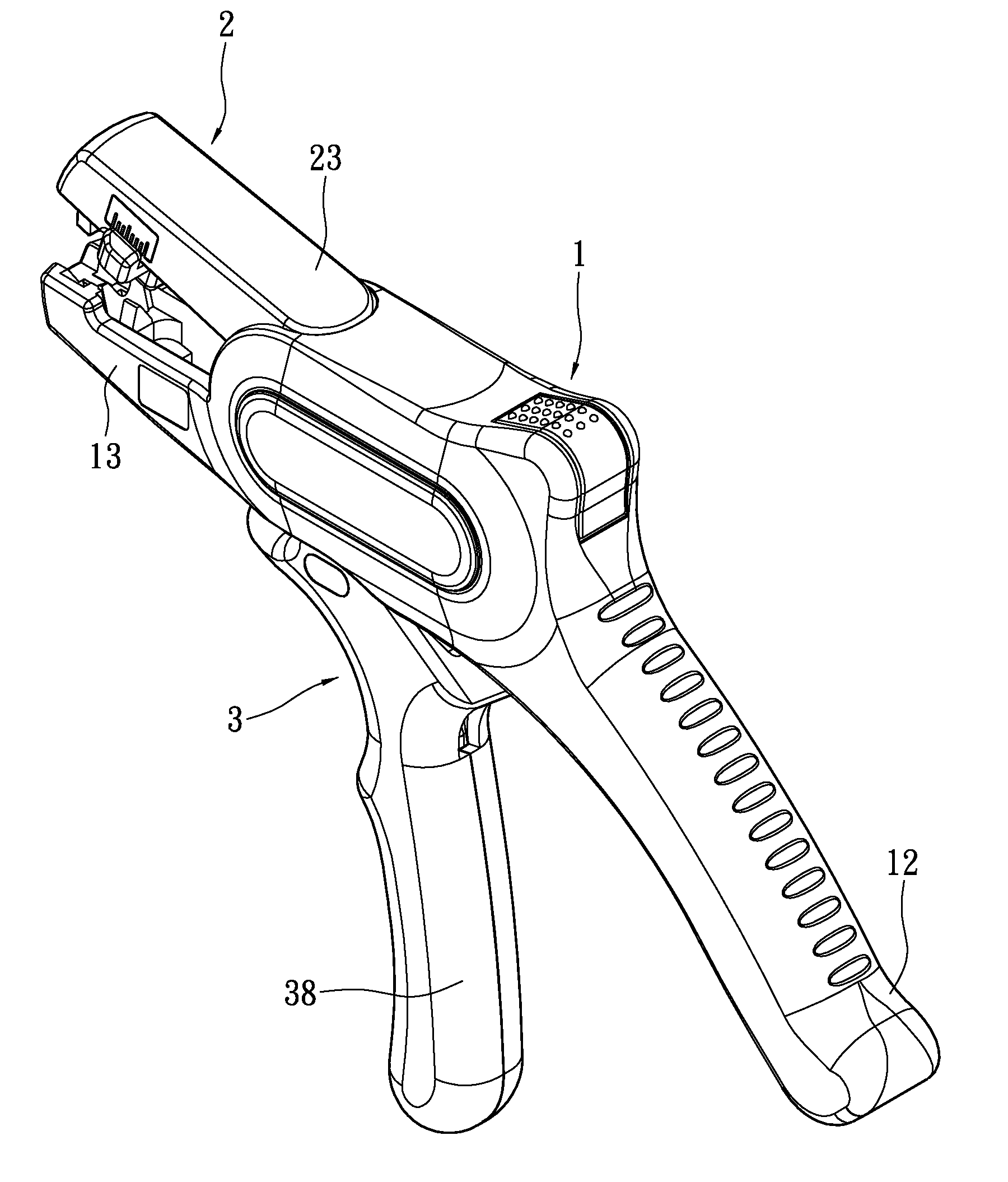
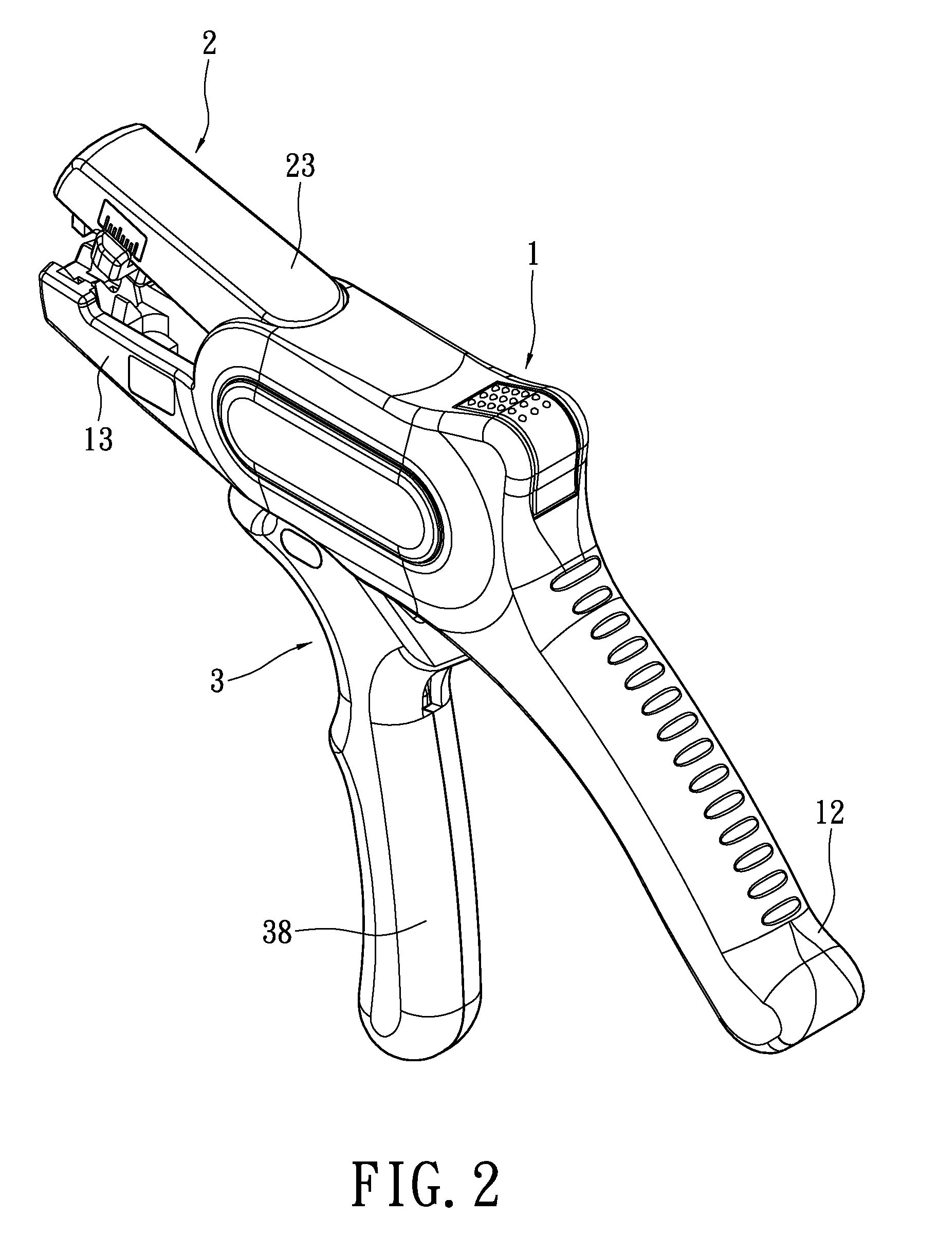
[0018]Please refer to FIGS. 2 to 4. The present invention provides a wire stripper, which includes a first main body 1, a second main body 2 and a third main body 3.

[0019]The first main body 1 has a main body portion 11, a rear grip 12, a lower engaging portion 13 and an accommodating space 14. Both sides of the main body portion 11 have a connecting hole 111 respectively. The connecting hole 111 is made throughout the main body portion 11. The front end and the rear end on both sides of the main body portion 11 have a locking hole 112 respectively. The connecting holes 111 and the locking holes 112 are symmetric with respect to each other in the left-and-right direction. The main body portion 11 further has two side covers 113. The front and rear ends of the inner surface of the side cover 113 have a locking piece 114 respectively. The side cover 113 is connected to the main body portion 11 by means of the locking piece 114 being engaged with the locking holes 112. The rear grip 12...


PUM

PropertyMeasurementUnit
lengthaaaaaaaaaa
forceaaaaaaaaaa
elastic forceaaaaaaaaaa

Abstract

A wire stripper includes: a first main body having a main body portion, a rear grip, a lower engaging portion and an internal accommodating space; a second main body having an outer casing, an inner casing received in the outer casing, two upper engaging portions, two first rail holes located on both sides of the outer casing, two second rails, two first rails located on both sides of the inner casing and two second rail holes; and a third main body having a left casing and a right casing combined with each other, a front grip extending downwards from the left casing and the right casing, an acting portion connected between the second main body and the third main body, and a spring portion abutting in the front grip and the rear grip. The second main body and the third main body are received in the accommodating space.

Description

BACKGROUND OF THE INVENTION[0001]1. Field of the Invention[0002]The present invention relates to a wire stripper, and in particular to a wire stripper capable of stripping off insulating surfaces of various wires and easy to operate.[0003]2. Description of Related Art[0004]FIG. 1 shows a conventional wire stripper. A clipping body 4 of the wire stripper includes a left clipper 41 and a right clipper 42 corresponding to each other. The top of the left clipper 41 has a clamping portion 411. A clamping base 412 is provided below the clamping portion 411. The top of the right clipper 2 has a knife 421. A knife base 422 is provided below the knife 421. A positioning portion 423 is provided below the knife base 422. The positioning portion 423 is adjacent to an adjusting portion 424 for adjusting the length of the insulating surface of a wire to-be-stripped. A pivoting portion 43 is pivotally connected between the left clipper 41 and the right clipper 42. Each of the bottom ends of the le...

Claims


Application Information

Patent Timeline
Patent Type & Authority Patents(United States)
IPC IPC(8): H02G1/12
CPCH02G1/1212
Inventor YEN, CHAO-CHIN
Owner KAUW YEHI IND CO LTD
Why Eureka
Try Eureka