Tire pressure monitoring system using wireless network

a technology of tire pressure monitoring and wireless network, applied in vehicle wireless communication service, tire measurement, electric signalling details, etc., can solve the problems of complex installation and operation procedures, difficult valve positioning, and inability to meet the needs of vehicles,

Active Publication Date: 2012-01-17
MEASUREMENT
View PDF81 Cites 43 Cited by
  • Summary
  • Abstract
  • Description
  • Claims
  • Application Information

AI Technical Summary

Problems solved by technology

At night, it is difficult to locate the valve.
While some vehicles have systems for monitoring of tire pressure using tire pressure gauges with radio-frequency transmitters pre-installed in the tires, and systems for interrogating the gauges and receiving readings installed in the vehicle, such systems have significant drawbacks including multiple, integrated components, complicated installation and operating procedures and impractical retrofitting on existing vehicles.

Method used


Image

  • Tire pressure monitoring system using wireless network
  • Tire pressure monitoring system using wireless network
  • Tire pressure monitoring system using wireless network

Examples


Embodiment Construction

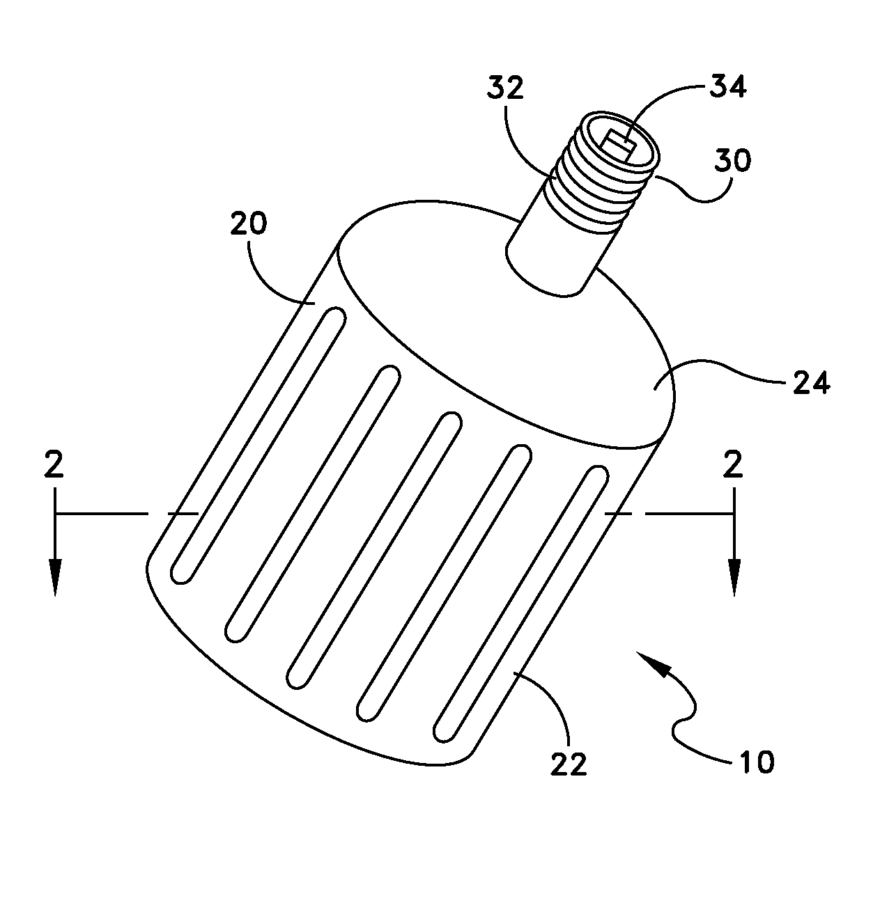
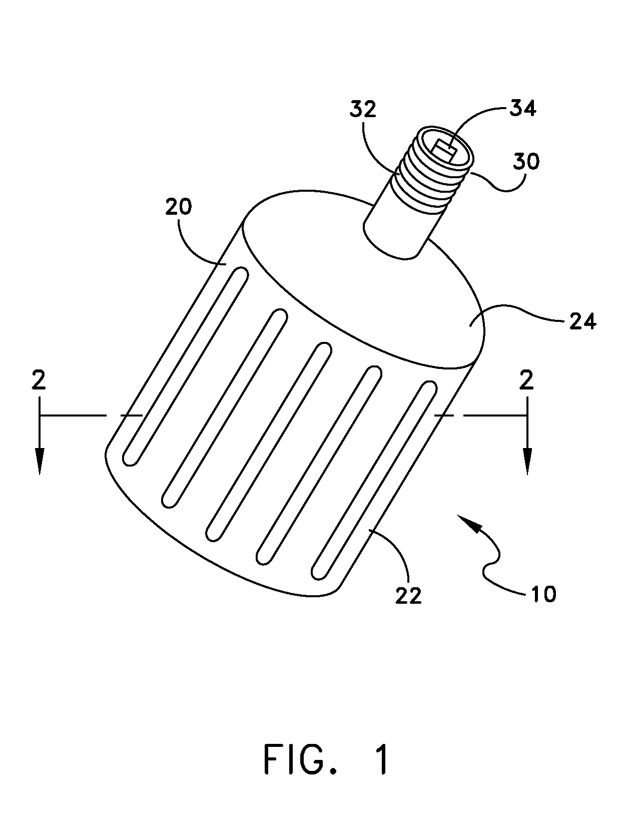
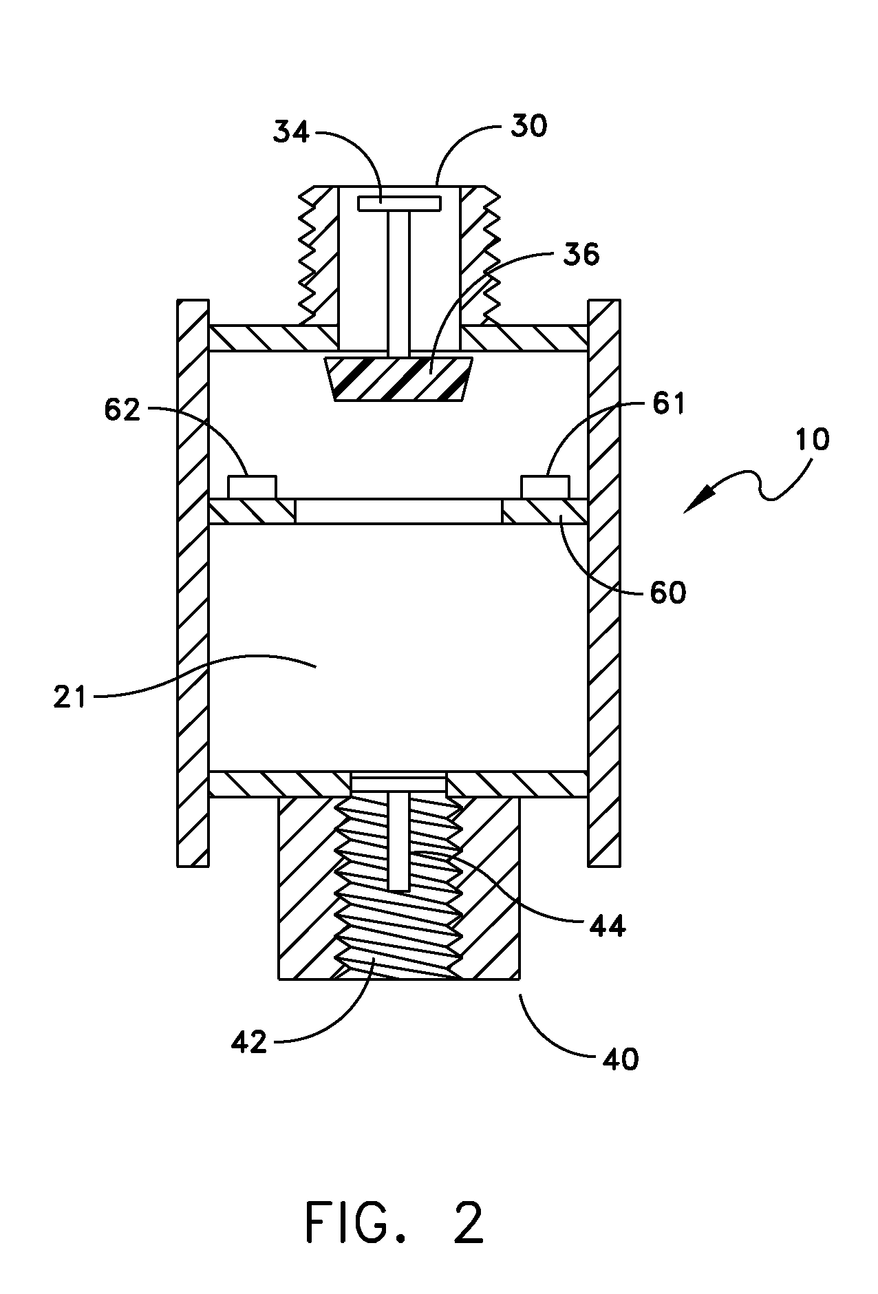
[0032]It is to be understood that the figures and descriptions of the present invention have been simplified to illustrate elements that are relevant for a clear understanding of the present invention, while eliminating, for purposes of clarity, many other elements found in typical tire pressure gauges and tire pressure measurement and monitoring systems. However, because such elements are well known in the art, and because they do not facilitate a better understanding of the present invention, a discussion of such elements is not provided herein. The disclosure herein is directed to all such variations and modifications known to those skilled in the art.

[0033]Further, it should be understood that the several views of the housings, displays and general configurations shown in the figures include many decorative or ornamental features, aspects of which the particulars may be changed while maintaining the device's utility and without departing from the scope and spirit of the present ...


PUM


Abstract

A tire pressure monitoring using wireless network includes a remote command device and a valve-stem mountable tire pressure gauge. The tire pressure gauge includes a pressure sensor for detecting a pressure of a fluid in a tire and providing an output signal indicative of the detected fluid pressure, and a first radio-frequency module for transmitting data indicative of the detected fluid pressure based on the output signal of the pressure sensor. The remote command device includes a second radio-frequency module for wirelessly receiving the data transmitted by the data transmitted by the first radio frequency module, a wireless communication module for communicating via a wireless network, information based at least one data received by the second radio frequency module, and a display for displaying at least the fluid pressure detected by the pressure sensor.

Description

REFERENCE TO CROSS-RELATED APPLICATIONS[0001]This application is a continuation-in-part of and claims benefit of U.S. patent application Ser. No. 12 / 259,046, entitled “COMBINED TIRE PRESSURE GAUGE AND REMOTE TIRE PRESSURE DISPLAY” and filed on Oct. 27, 2008, which application claims benefit of U.S. Provisional Patent Application No. 61 / 000,579, filed on Oct. 26, 2007, all of which applications are hereby incorporated by reference herein in their entireties. This application also claims the benefit of U.S. Provisional Patent Application No. 61 / 229,261, entitled “TIRE PRESSURE MONITORING SYSTEM USING WIRELESS NETWORK’ and filed Jul. 28, 2009, which application is hereby incorporated by reference herein in its entirety.FIELD OF INVENTION[0002]The present invention relates to pressure measurement and pressure gauges and particularly to tire pressure monitoring systems.BACKGROUND[0003]Pressure gauges are conventionally used for measuring the pressure of a gas or a liquid, such as an air ...

Claims


Application Information

Patent Timeline
Patent Type & Authority Patents(United States)
IPC IPC(8): B60C23/00G08B1/08H04W4/40
CPCB60C23/0401B60C23/0408B60C23/0496G01L17/00B60C23/00
Inventor PETRUCELLI, STEVENKUSKOVSKY, MARK
Owner MEASUREMENT
Why Eureka
Try Eureka