Sealed secondary battery, and method for manufacturing the battery

a secondary battery and sealing technology, applied in the field of sealed secondary batteries, can solve the problems of inability to completely seal the opening, short circuit, internal short, etc., and achieve the effect of stable, reliable and reduced sputtering

Active Publication Date: 2012-01-31
PANASONIC CORP
View PDF21 Cites 6 Cited by
  • Summary
  • Abstract
  • Description
  • Claims
  • Application Information

AI Technical Summary

Benefits of technology

[0019]With this configuration, even with a variation in external factors in fabrication processes in welding between the lead and the sealing plate, a joint strength between the lead and the sealing plate can be maintained with sputtering during laser welding being reduced. In this manner, a stable, reliable sealed secondary battery can be obtained.

Problems solved by technology

If these sputtered substances enter the electrode group in the battery case, the separator might be damaged, resulting in an internal short.
Consequently, the battery case and the sealing plate come into contact with each other while sandwiching the adhering substances therebetween, resulting in a short circuit.
However, the opening cannot be completely sealed, and thus, such covering is insufficient for preventing contamination by sputtered substances.
However, joining by ultrasonic welding exhibits a lower joint strength than that obtained by the resistance welding.
In addition, if the sealing plate has a safety mechanism for explosion protection, ultrasonic vibration might affect the function of the safety mechanism.
Further, joining by ultrasonic welding is not preferable in reliability because an active material might be peeled off from the electrode plate.
Accordingly, a large current needs to flow for a short period in resistance welding, resulting in that a welding rod badly wears, and it is difficult to maintain a stable joint for a long period.

Method used


Image

  • Sealed secondary battery, and method for manufacturing the battery
  • Sealed secondary battery, and method for manufacturing the battery
  • Sealed secondary battery, and method for manufacturing the battery

Examples


first embodiment

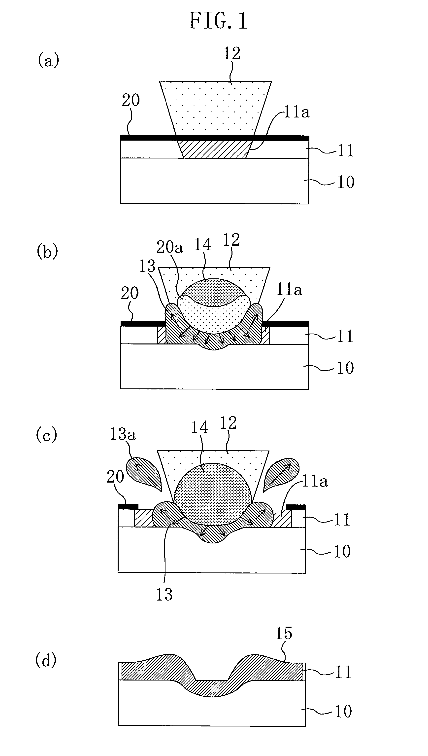
[0066]FIGS. 6(a)-6(d) are cross-sectional views schematically illustrating a process of laser-welding a lead 11 to a sealing plate 10 according to a first embodiment of the present invention.

[0067]As illustrated in FIG. 6(a), the lead 11 is irradiated with a fiber laser beam (hereinafter simply referred to as a “laser beam”) 12 with the lead 11 brought into contact with the sealing plate 10, thereby heating a laser-irradiated region 11a of the lead 11. The laser beam 12 has a spot diameter smaller than the thickness of the lead 11.

[0068]As illustrated in FIG. 6(b), the heated region 11a partially melts to form a melted portion 13, and an evaporation repulsive force of metal vapor from the melted lead 11 forms a keyhole. Then, as illustrated in FIG. 6(c), as the keyhole further grows, the melted portion 13 is also extended beyond the surface of the sealing plate 10. Thereafter, when the irradiation with the laser beam 12 is stopped, the melted portion 13 is hardened to fill the keyho...
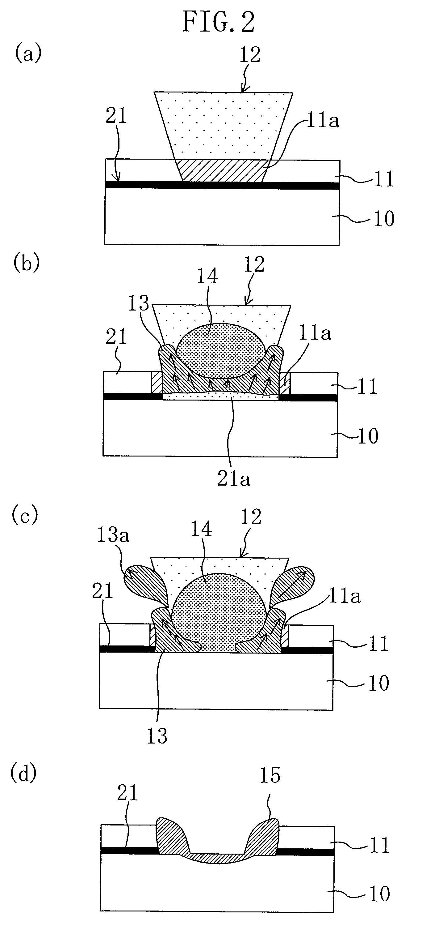
second embodiment

[0081]The spot diameter of a fiber laser is about 1 / 10 of that of a YAG laser. Thus, the joint strength might decrease as the welding area decreases. Accordingly, a large number of welded portions are necessary for ensuring a sufficient joint strength. However, laser welding of a plurality of portions with a laser beam producing pulse oscillation causes repetitive state changes among heating, melting, and solidification, resulting in that sputtering readily occurs. In addition, some welded portions might be unstable, and as a result, a stable joint strength might not be obtained.

[0082]In view of these problems, in order to obtain a stable joint structure without occurrence of sputtering, a technique for forming a linear melted portion by performing continuous scanning with a continuously oscillating fiber laser is proposed in this embodiment. With this technique, a joint structure having a joint strength almost equal to or greater than the joint strength obtained with a YAG laser ca...

third embodiment

[0096]The inventors of the present invention conducted keyhole joining between a lead 11 and a sealing plate 10 with a method according to the present invention, and studied the resultant joint structure, to find out the following phenomena.

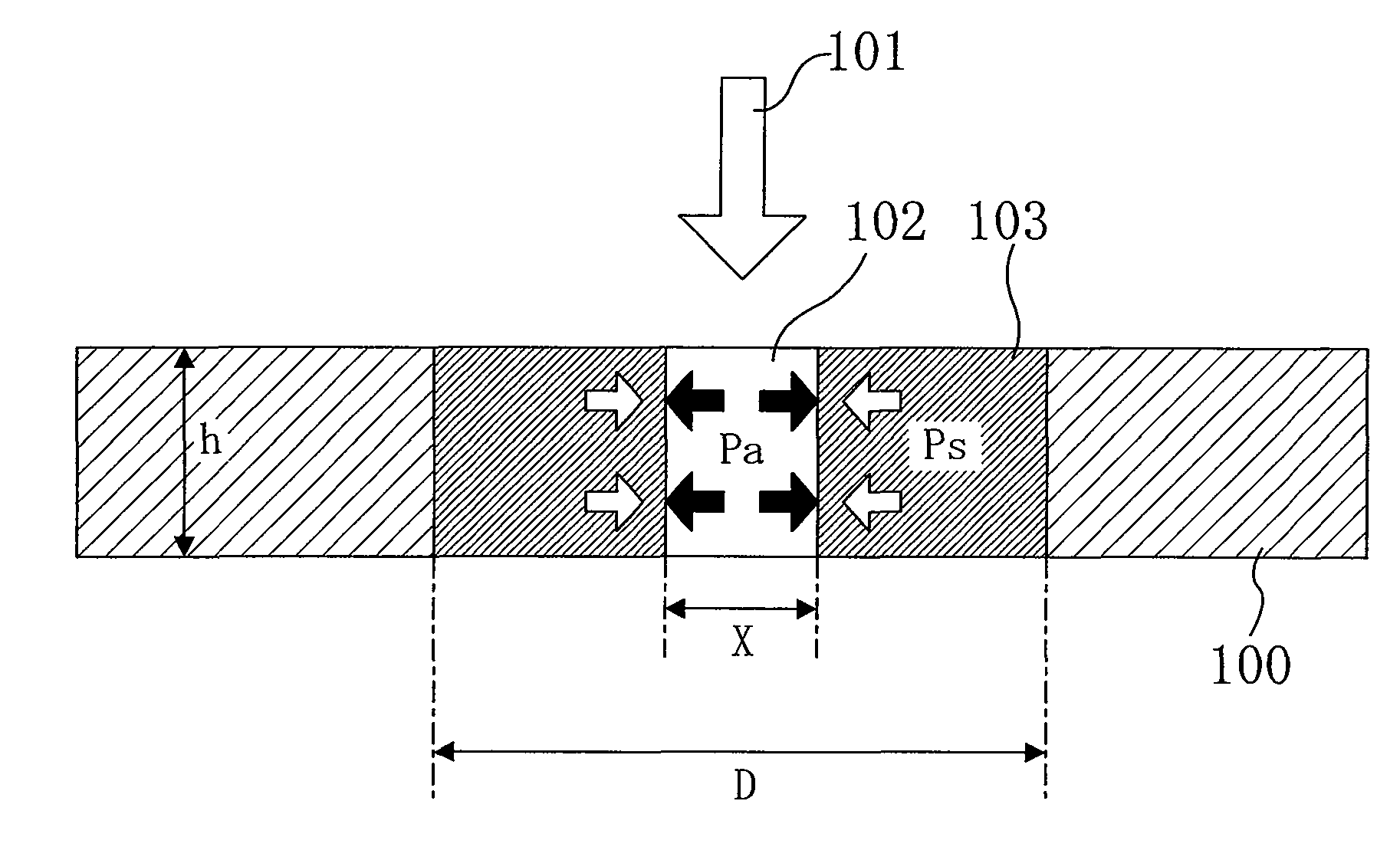
[0097]As illustrated in FIG. 7(a), an end of the lead 11 (made of aluminium foil with a thickness of 0.15 mm and a width of 4 mm) extending from an electrode group was brought into contact with the sealing plate 10 (made of an aluminium plate with a thickness of 0.1 mm in a portion welded to the lead 11, and a diameter of 16.8 mm). In this state, the lead 11 was irradiated with a laser beam having a spot diameter of 0.02 mm and a power density of 7×10⁷ W / cm2, while being scanned along the width of the lead 11 at a scanning speed of 10 m / min. In this manner, laser welding was performed on the lead 11 and the sealing plate 10, and a joint structure of the resultant welded portion 15 was observed.

[0098]FIGS. 15(a)-15(d) show the results of the above...


PUM

PropertyMeasurementUnit
thicknessaaaaaaaaaa
diameteraaaaaaaaaa
thicknessaaaaaaaaaa

Abstract

An electrode group 4 formed by stacking or winding a positive electrode plate 1 and a negative electrode plate 2 with a separator 3 interposed therebetween, is housed in a battery case 5. An opening of the battery case 5 is sealed with a sealing plate 10. A lead 11 extending from one of the positive and negative electrode plates in the electrode group 4 is laser-welded to the sealing plate 10 by application of a laser beam 12 having a spot diameter smaller than a thickness of the lead 11.

Description

RELATED APPLICATIONS[0001]This application is the U.S. National Phase under 35 U.S.C. §371 of International Application No. PCT / JP2009 / 002854, filed on Jun. 23, 2009, which in turn claims the benefit of Japanese Application Nos. 2008-205418, filed on Aug. 8, 2008, 2008-209836, filed on Aug. 18, 2008, 2008-209838, filed on Aug. 18, 2008, and 2008-275166, filed on Oct. 27, 2008, the disclosures of which Applications are incorporated by reference herein.TECHNICAL FIELD[0002]The present invention relates to sealed secondary batteries and methods for fabricating sealed secondary batteries, and more particularly to a joint structure between a sealing plate and a lead extending from an electrode group.BACKGROUND ART[0003]Sealed secondary batteries, including aqueous electrolyte secondary batteries typified by high-capacity alkaline storage batteries and nonaqueous electrolyte secondary batteries typified by lithium-ion secondary batteries, are widely used as power sources for driving mobil...

Claims


Application Information

Patent Timeline
Patent Type & Authority Patents(United States)
IPC IPC(8): H01M10/00B23K26/00H01M4/04H01M2/22B23K26/21H01M10/34H01M50/528H01M50/534H01M50/536H01M50/538H01M50/54
CPCB23K26/206H01M2/043H01M2/263H01M2/266H01M2/305B23K26/32B23K26/082B23K26/244B23K2203/10Y10T29/4911Y10T29/49108B23K2103/10Y02E60/10H01M50/538H01M50/54H01M50/534H01M50/536H01M50/543H01M50/531B23K26/04B23K26/24
Inventor MIYATA, KYOSUKEFUKUOKA, TAKAHIROHARIMA, YUKIOFUNAMI, KOJIKUMAZAWA, SEIJI
Owner PANASONIC CORP
Why Eureka
Try Eureka