Collapsible pet bowl

Inactive Publication Date: 2012-02-07
FISHPOND
18 Cites 9 Cited by

AI-Extracted Technical Summary

Problems solved by technology

While such containers in a home environment are typically of rigid construction, dimensional aspects can hinder transport—especially so for hiking, backpacking and other outdoor endeavors.
However, such articles are not without problems and deficiencies.
For i...

Method used

[0029]With reference to FIGS. 10 and 11, bowl 10—with collapsed sidewall component 12—can be dimensioned to be positioned through open sheath component 32 of bowl 24. With bottom component 14 of bowl 10, or another apparatus or travel component suitably configured, within bottom component 28 of bowl 24, mechanism 36 can be moved along cord 38 to cinch sheath component 32. With convenient collapse of sidewall component 26,...

Benefits of technology

[0011]Accordingly, in part, this invention can also be directed to a method of using a travel pet bowl or another bowl of this invention for storage. Such a method can comprise providing a pet bowl of the sort described above, such a bowl apparatus comprising a sheath component; positioning another apparatus within the pet bowl apparatus; and collapsing a sidewall and a sheath component over the other apparatus. In certain embodiments, the bottom component of such a pet bowl apparatus can be coup...

Abstract

A collapsible bowl apparatus and related methods of use.

Application Domain

Animal feeding devicesAnimal housing +1

Technology Topic

Biomedical engineeringCompanion animal

Image

  • Collapsible pet bowl
  • Collapsible pet bowl
  • Collapsible pet bowl

Examples

  • Experimental program(1)

Example

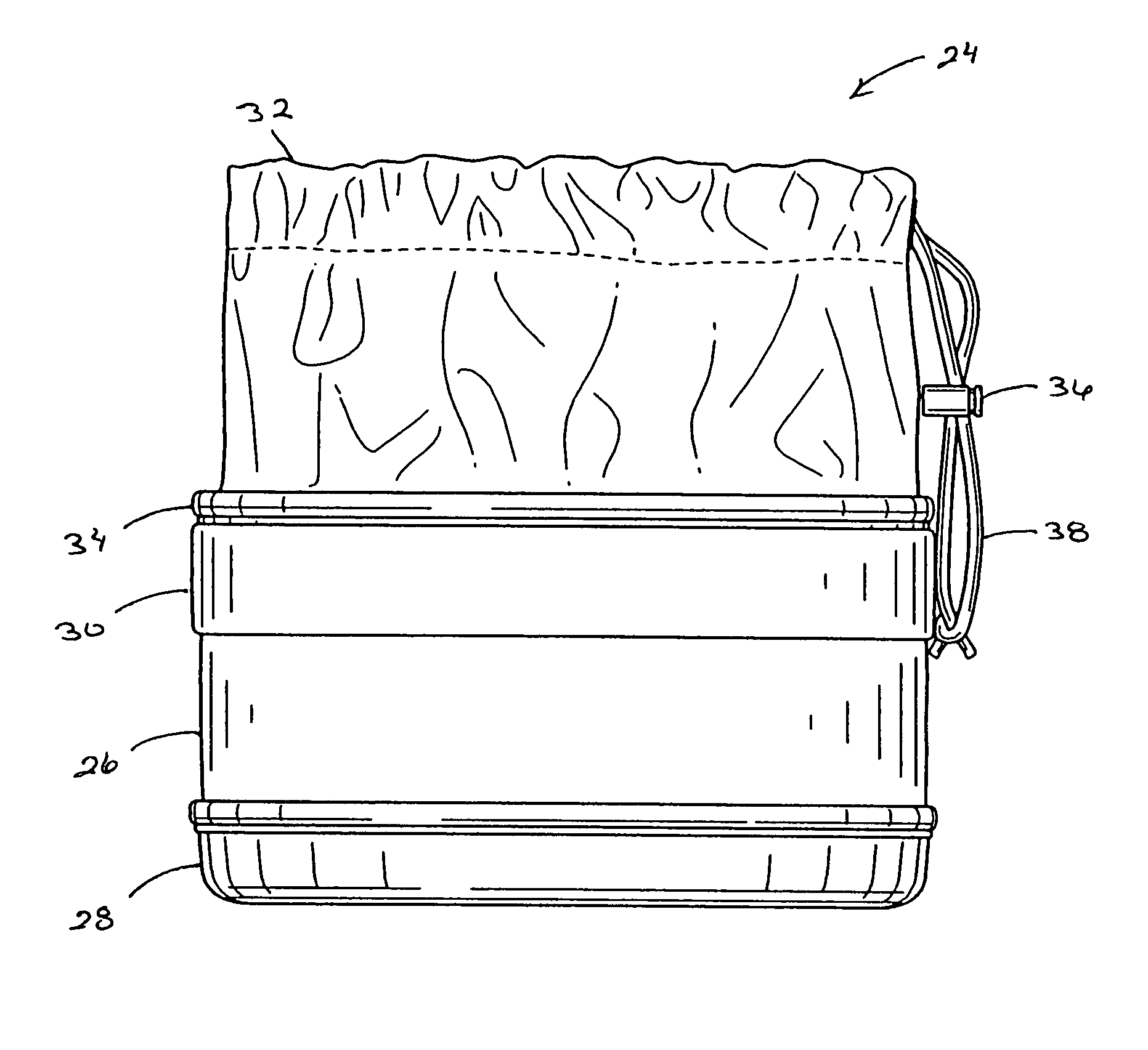
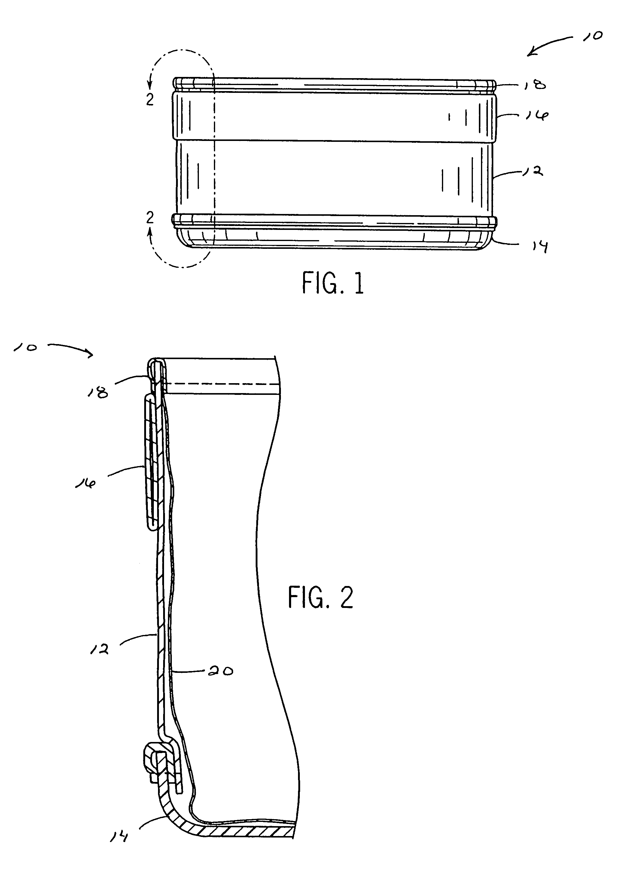
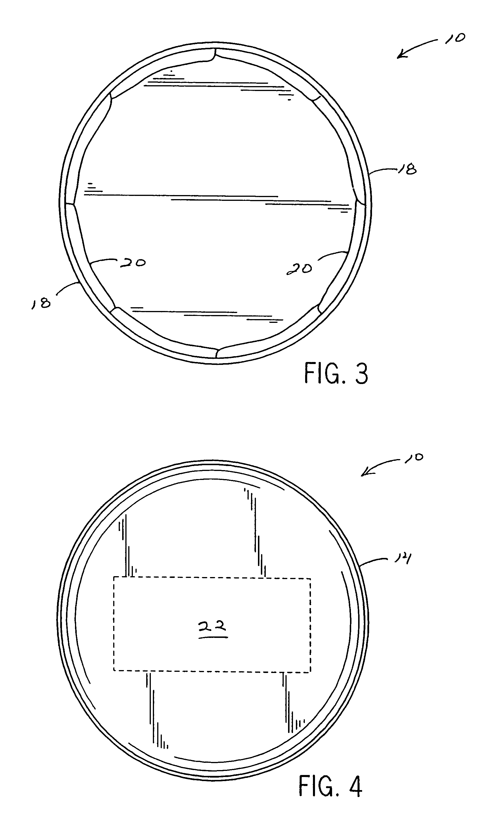
[0023]Various non-limiting features and aspects of the present invention can be illustrated with reference to FIGS. 1-11. Referring to FIG. 1, bowl 10 is configured with collapsible and/or deformable sidewall component 12 coupled to rigid bottom component 14. Component 12 can, optionally, be configured with band portion 16 variably positioned therealong, to provide additional structural support and/or for position of one or more of a variety of decorative aspects. Regardless, upper edge component 18, optionally of rigid or sturdy construction, can also serve to lend structural support to sidewall component 12.
[0024]A partial, cross-sectional side view of bowl 10 is provided in FIG. 2, along line 2-2 of FIG. 1. Accordingly, FIG. 2 illustrates but one possible construction of bowl 10, showing an inner liner component 20 along sidewall component 12 and bottom portion 14, upwardly coupled to the sidewall and as can be upwardly coupled to or integrated with sidewall component 12 and upper edge component 20. FIGS. 3 and 4, respectively, provide top and bottom views of bowl 10, with FIG. 3 illustrating a peripherally-rounded sidewall 12 and with FIG. 4 illustrating a peripherally-rounded bottom component 14, and optionally providing area 22 for a trademark or another informational designation incorporated therein. Upward extension of bottom portion 14 can provide added structural support to sidewall component 12.
[0025]Regardless of any particular article or component configuration, components 12-20 can be constructed of materials known in the art, such materials limited only by the functional attributes of each such described component herein. Without limitation, bottom component 14 can be constructed from a molded polymeric material. Without limitation, desired rigidity and/or non-skid texture can be provided through use of a polyethylene laminate, such a material as can be prepared using known compression molding techniques. Likewise, without limitation, inner component 20 can comprise one or more ply or layer components, constructed from a waterproof material or composite. In certain embodiments, a urethane-coated nylon material can be used with good effect.
[0026]Other representative embodiments of this invention can be illustrated with reference to FIG. 5. As shown therein, bowl 24 is configured with collapsible sidewall component 26 coupled to rigid bottom component 28. As discussed above, band portion 30 can be positioned along sidewall component 26. Integrated sheath component 32 is coupled to and extends from upper edge component 34 and can be closed or cinched upon action of mechanism 36 on drawstring or cord 38 positioned therein.
[0027]FIG. 7 provides a partial cross-sectional view of the bowl of FIG. 6, along line 7-7. As shown therein, drawstring/cord 38 is positioned within circumferential or peripheral loop 40 fashioned by sheath component 32. Inner liner component 42 can be positioned along sidewall component 26 and bottom component 28. Both sheath component 32 and liner component 42 can be coupled to or integrated with upper edge component 34. Various other component constructions and arrangements are possible.
[0028]FIGS. 8 and 9 show, respectively, top and bottom views of bowl 24. In particular, bottom component 28 can, optionally, provide for inclusion of a trademark designation and/or other information in area 44. Material choices for components 26, 28, 30 and 34 can be as described above. Sheath component 32 can comprise a pliable (e.g., nylon) material, with properties of the sort affording function as described below.
[0029]With reference to FIGS. 10 and 11, bowl 10—with collapsed sidewall component 12—can be dimensioned to be positioned through open sheath component 32 of bowl 24. With bottom component 14 of bowl 10, or another apparatus or travel component suitably configured, within bottom component 28 of bowl 24, mechanism 36 can be moved along cord 38 to cinch sheath component 32. With convenient collapse of sidewall component 26, bowl 10 can be configured for nesting with bowl 24, for convenient storage and/or transport. In certain embodiments, bowl 10 can be a pet water bowl, and bowl 24 can be a pet food bowl. As shown in FIG. 11, a nesting relationship of bowl 10 within bowl 24 can provide a compact arrangement for pet care and feeding away from home. Various embodiments of this invention are available from fishpond, LLC of Silverthorne, Colo.
[0030]While the principles of this invention have been described in connection with specific embodiments, it should be understood clearly that these descriptions are added only by way of example and are not intended to limit, in any way, the scope of this invention. For instance, the present invention contemplates various other bowl shapes and/or geometric configurations, such shapes, as well as other component proportions, configurations and proportions, as well as end-use applications, such shapes, configurations and uses limited only by function and utility of the sort described herein.

PUM

no PUM

Description & Claims & Application Information

We can also present the details of the Description, Claims and Application information to help users get a comprehensive understanding of the technical details of the patent, such as background art, summary of invention, brief description of drawings, description of embodiments, and other original content. On the other hand, users can also determine the specific scope of protection of the technology through the list of claims; as well as understand the changes in the life cycle of the technology with the presentation of the patent timeline. Login to view more.
Why Eureka
Try Eureka