Osteosynthesis plate

a plate and plate body technology, applied in the field of osteosynthesis plates, can solve the problems of not meeting simultaneously, affecting the production of said portions, and the possibility of movement of bone parts, etc., and achieve the effect of simple production of said portions and easy and quick mounting on the pla

Active Publication Date: 2012-02-14
MEDICREA TECH
View PDF15 Cites 18 Cited by
  • Summary
  • Abstract
  • Description
  • Claims
  • Application Information

AI Technical Summary

Benefits of technology

[0016]a sliding nut engaged in said slot, said nut having a thickness smaller than that of the second area but greater than that of the first area, able to be moved from this second area toward the first area in such a way as to bring said portion of material from its withdrawn position to its active position.
[0028]Preferably, each sliding nut comprises means enabling it to be latched through said second area of the slot, such that its insertion on the plate is simple. When multiple such sliding nuts are connected to a same piece, in particular when the plate comprises the aforementioned ring, this piece is easily and quickly mounted on the plate by engagement and latching of the various sliding nuts in the corresponding second areas of the various slots.

Problems solved by technology

This type of fixing may, in some cases, involve a risk of the screws coming unscrewed, which leads to the possibility of movement of the bone parts that are supposed to be maintained by the plate.
The existing systems, however, have the drawback of not simultaneously meeting the following needs:simplicity of structure and relative ease of production;reduced production cost;ease and speed of implementation;perfect anti-backout action of the screws;possible reversibility of this anti-backout action, in the case where one or several screws must be removed.

Method used


Image

  • Osteosynthesis plate
  • Osteosynthesis plate
  • Osteosynthesis plate

Examples


Embodiment Construction

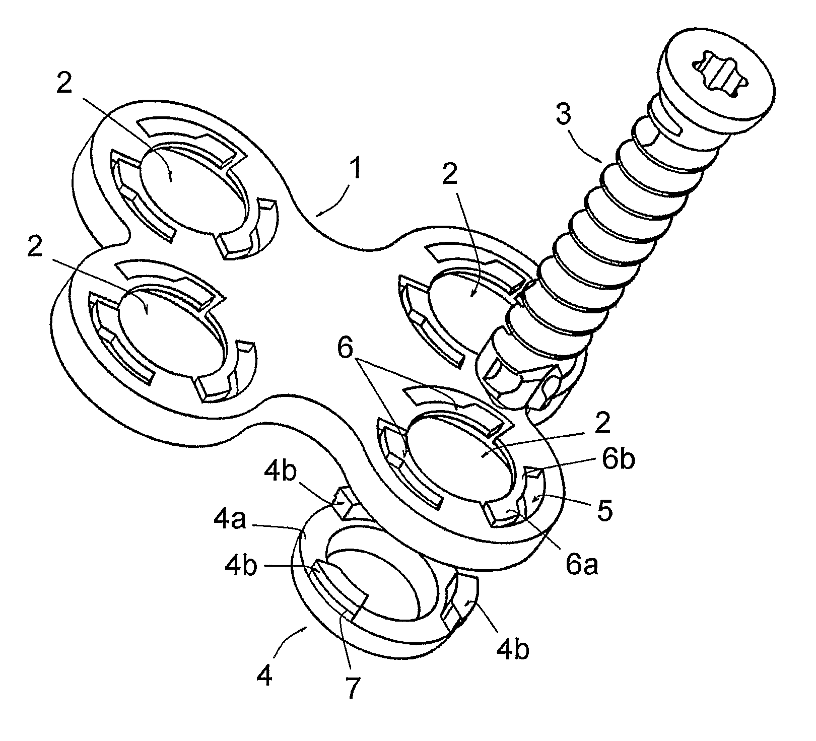
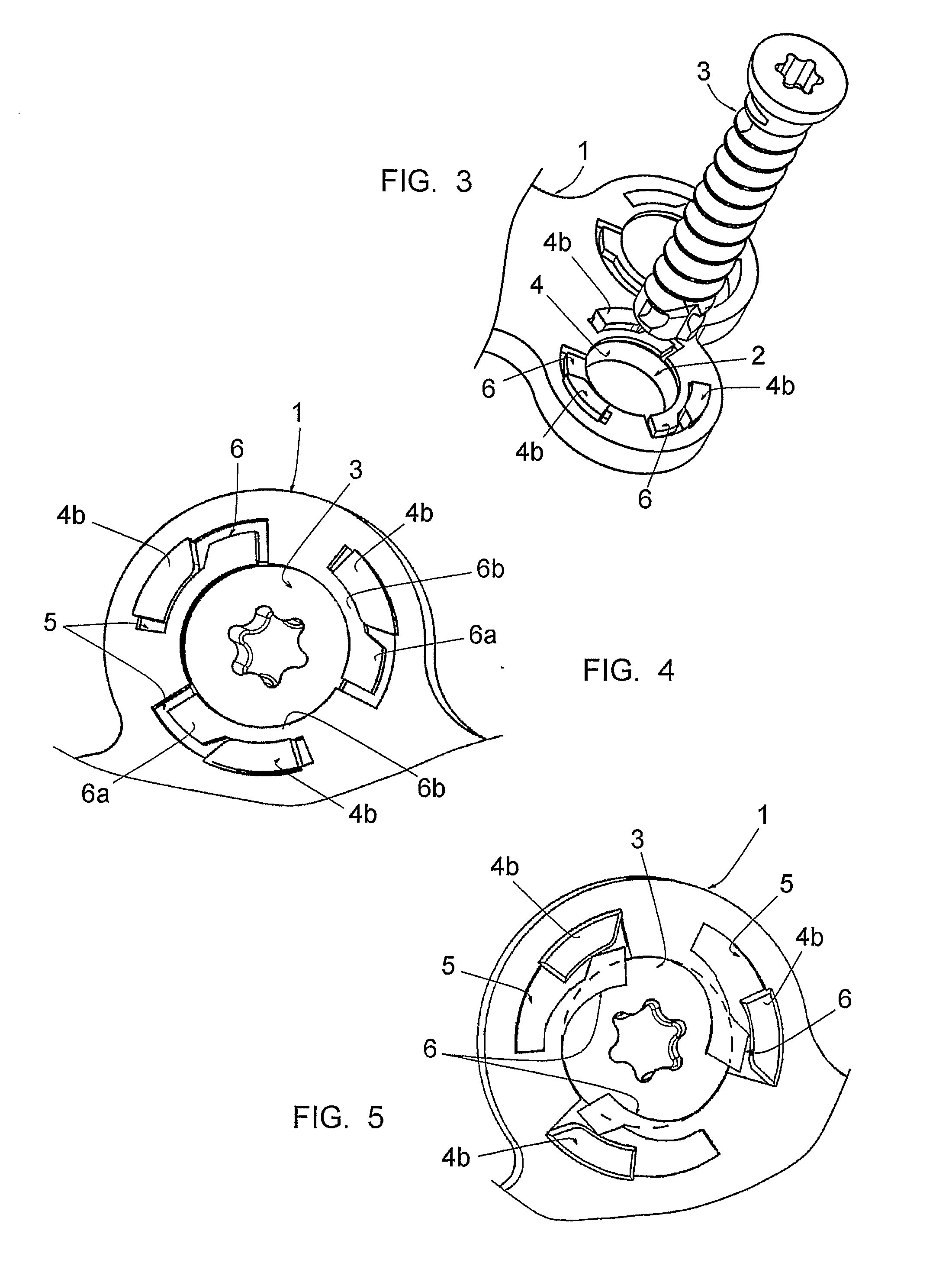
[0035]FIG. 1 shows an osteosynthesis plate 1, in particular for osteosynthesis of cervical vertebrae, comprising four holes 2 for its fixing to two consecutive cervical vertebrae using screws 3 engaged in these holes, only one screw 3 being illustrated. This plate 1 is made of a suitable metallic material, particularly stainless steel or titanium.

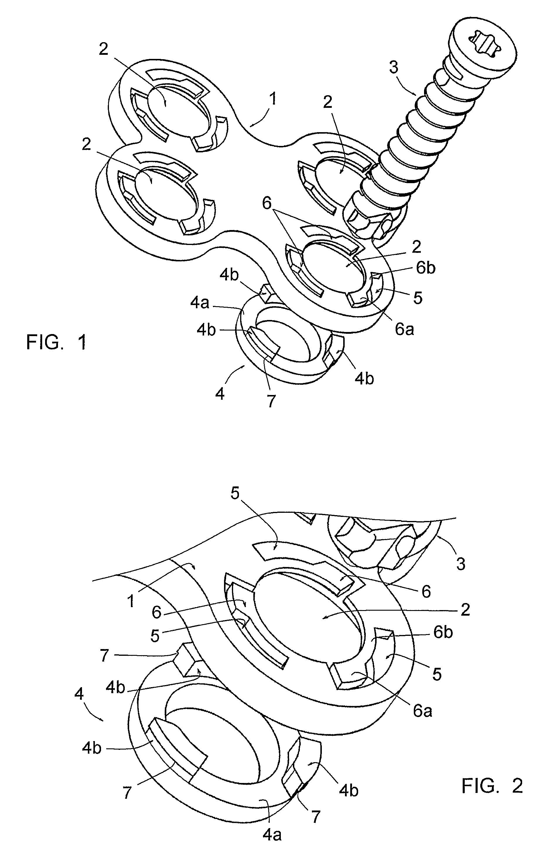
[0036]As is shown more specifically in FIG. 2, the plate comprises four bores coaxial to the holes 2, reducing its thickness at the level of these holes 2 and forming housings to receive four rings 4, only one of which is illustrated in FIG. 1.

[0037]In its residual thickness, the plate 1 comprises, at the level of each hole 2, three slots 5 distributed regularly on the circumference of the hole 2.

[0038]Each slot 5 comprises a first portion, developed radially in relation to the hole 2 and opening into this hole, and a second portion, curved, extending on a sector of this hole 2 at a distance from the edge defining this hole, the slot 5 ther...


PUM


Abstract

A plate (1) includes blocking elements (4b, 5, 6) including:at least one slot (5) comprising a first portion opening into the hole (2) and a second portion extending over a section of this hole (2), at a distance from the edge defining this hole (2), this slot (5) thereby isolating a portion of material (6); this portion (6) has a first part (6a) with a radially increased thickness and a second part (6b) having a radially reduced thickness; this part (6b) has a thickness such that the portion (6) may be radially mobile between a withdrawn position and an active position;a pad (4b) engaged in the slot (5), able to be moved in such a way as to bring the portion of material (6) from its withdrawn position to its active position.

Description

BACKGROUND OF THE INVENTION[0001]1. Field of the Invention[0002]The present invention relates to an osteosynthesis plate, in particular for vertebral osteosynthesis, and in particular a plate intended for the osteosynthesis of cervical vertebrae.[0003]2. Description of the Related Art[0004]An osteosynthesis plate is generally fixed using screws engaged through holes formed in the plate. This type of fixing may, in some cases, involve a risk of the screws coming unscrewed, which leads to the possibility of movement of the bone parts that are supposed to be maintained by the plate. This is particularly the case for an osteosynthesis plate for cervical vertebrae, given that these vertebrae are subject to repeated stress and that the extent to which the screws are supported in these vertebrae is reduced due to the reduced dimensions of these screws.[0005]A number of systems have been conceived making it possible to prevent the back-out of screws from osteosynthesis plates, for example b...

Claims


Application Information

Patent Timeline
Patent Type & Authority Patents(United States)
IPC IPC(8): A61B17/80
CPCA61B17/7059A61B17/8033A61B17/8042
Inventor SOURNAC, DENYSCAFFIERO, JEAN-PHILIPPECARLIER, FRANCOIS
Owner MEDICREA TECH
Why Eureka
Try Eureka