Seat occupancy sensor

a seat occupancy and sensor technology, applied in the field of seat occupancy sensors, can solve the problems of the above-mentioned occupancy recognition system being relatively expensive, and achieve the effect of precise classification of seat occupancy detected

Active Publication Date: 2012-02-14
IEE INT ELECTRONICS & ENG SA +1
View PDF38 Cites 11 Cited by
  • Summary
  • Abstract
  • Description
  • Claims
  • Application Information

AI Technical Summary

Benefits of technology

[0011]The connection in a circuit according to the invention of at least two switch elements arranged with some distance between them thus enables particularly simple detection of seat occupancy, capable of distinguishing between local and wide-area occupancy of the seat without the need for a costly matrix circuit and a costly evaluating processor unit.
[0013]In a particularly simple embodiment, the switch elements may take the form of simple switches, such as membrane switches, for example. In an advantageous embodiment of the invention, the first and / or second switch element comprises a pressure sensor. In this embodiment, in addition to detection of occupancy, information about the intensity of the pressure exerted can also be obtained, enabling more precise classification of the seat occupancy detected.
[0018]It should be noted that each individual switching cell preferably comprises a pressure sensor, so that information about the intensity of the pressure exerted can also be obtained, enabling more precise classification of the seat occupancy detected.

Problems solved by technology

Nevertheless, the system for occupancy recognition described above is relatively costly, both as regards the circuitry of the individual switch elements and the construction of the evaluating processor unit.

Method used


Image

  • Seat occupancy sensor
  • Seat occupancy sensor
  • Seat occupancy sensor

Examples


Embodiment Construction

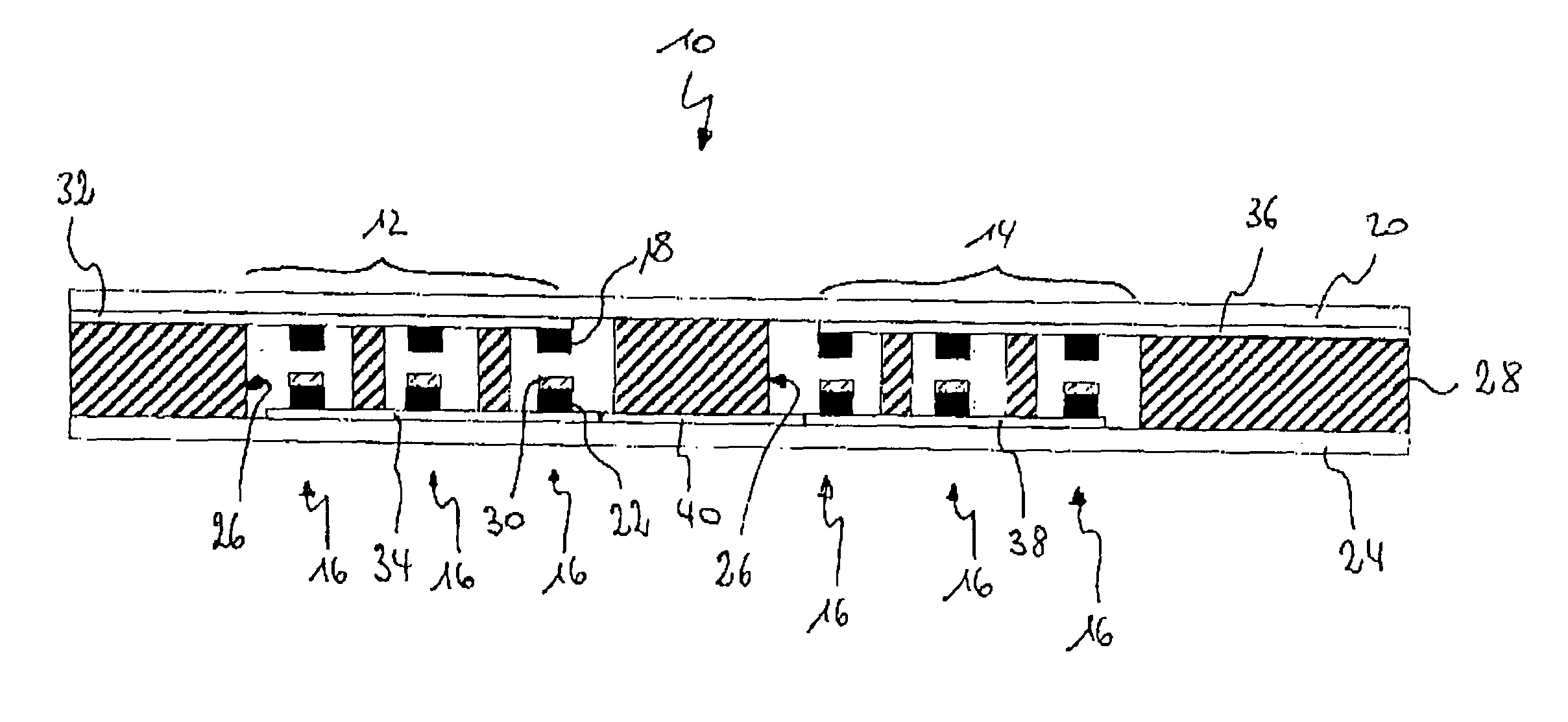
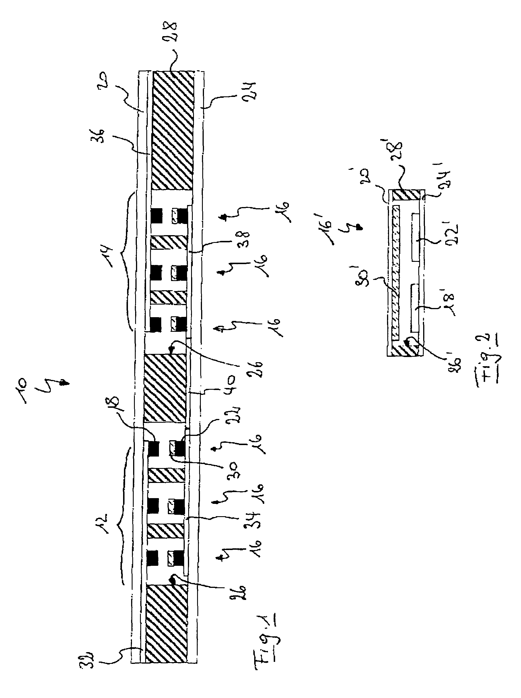
[0027]A first embodiment of a seat occupancy sensor 10 is shown in cross-section in FIG. 1. This is an embodiment using foil-type pressure sensors in what is called “through-mode”.

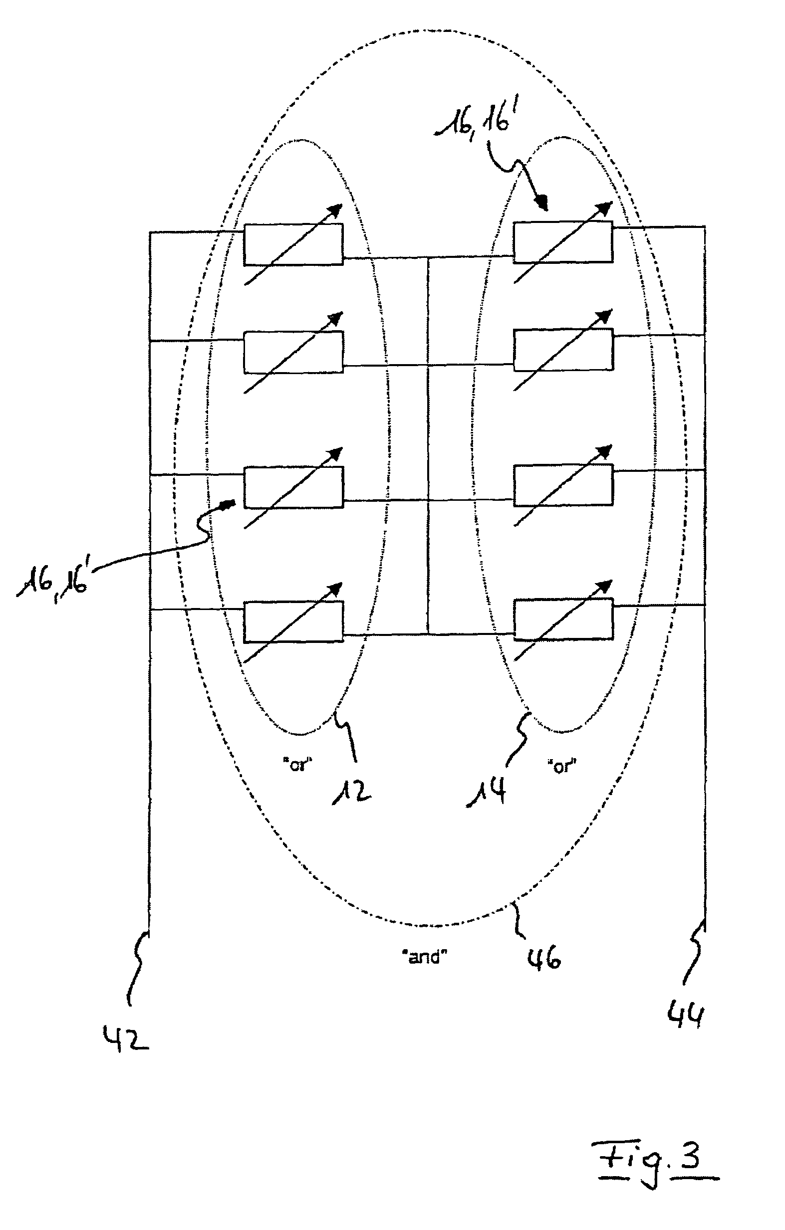
[0028]The seat occupancy sensor 10 shown comprises a first switch element 12 and a second switch element 14, each comprising a plurality of individual sensor cells 16.

[0029]Each sensor cell 16 comprises a first electrode 18 arranged on a first supporting foil 20 and a second electrode 22 arranged on a second supporting foil 24. The two supporting foils 20 and 24 are arranged by means of a spacer 28 provided with a recess 26 in such a way that the first electrode 18 and the second electrode 22 of each sensor cell 16 are positioned opposite each other and with a certain distance between them inside one of the recesses 26.

[0030]A layer 30 of some pressure-sensitive material, e.g. a suitable semi-conductive material, is applied in each sensor cell 16 to one of the electrodes, as it might be electrode 22, so th...


PUM


Abstract

The invention relates to a seat occupancy sensor (10) comprising at least two switch elements (12, 14) which can be activated by pressure. Said elements can be associated with the surface of a seat and are arranged at a certain distance from each other in such a manner that a first switch element (12) is associated with a first area of the seat and a second switch element (14) is associated with a second area of the seat. According to the invention, the first and second switch elements (12, 14) are connected to each other in such a manner that a logical AND-linkage is produced. The first and second switch elements are, for example, serially connected in a particularly simple embodiment of the invention.

Description

TECHNICAL FIELD OF THE INVENTION[0001]The invention concerns a seat occupancy sensor, especially for use in recognition of seat occupancy in a motor vehicle.BRIEF DESCRIPTION OF THE RELATED ART[0002]Seat occupancy sensors have been used for some time in motor vehicles for purposes of airbag control. By means of these seat occupancy sensors, the state of occupancy of a motor vehicle seat is determined, and the airbag allocated to a given seat is only activated if the current state of occupancy of the seat warrants such activation. These seat occupancy sensors in general present a plurality of switch elements, for example pressure sensors, in an arrangement distributed in the sitting surface of the motor vehicle seat. An evaluating processor unit connected to the seat occupancy sensor queries the circuit status of each individual switch element, and from the circuit status of each of the seat occupancy sensors, determines the occupancy state of the seat. If the seat is occupied by a p...

Claims


Application Information

Patent Timeline
Patent Type & Authority Patents(United States)
IPC IPC(8): G08B21/00B60N2/90B60R21/01B60R21/015
CPCB60R21/01516B60R21/01532B60R21/015B60R21/01B60R21/16
Inventor LORENZ, HOLGERHENZE, KARSTEN
Owner IEE INT ELECTRONICS & ENG SA
Why Eureka
Try Eureka