Fail-safe air flap control apparatus for vehicle

a control apparatus and air flap technology, applied in the direction of machine/engine, process and machine control, roof, etc., can solve the problems of air flaps not being able to maintain the completely open state but continuously flapping, severe engine cooling problems, etc., to prevent the engine from overheating

Inactive Publication Date: 2012-02-21
HYUNDAI MOTOR CO LTD +2
View PDF4 Cites 21 Cited by
  • Summary
  • Abstract
  • Description
  • Claims
  • Application Information

AI Technical Summary

Benefits of technology

[0018]Accordingly, the present invention has been made keeping in mind the above problems occurring in the prior art, and an object of the present invention is to provide a fail-safe air flap control apparatus for a vehicle which is constructed such that even if an electric device, such as an actuator, a solenoid unit, etc., malfunctions, an air flap can be maintained in the open state, thus preventing the engine from overheating.

Problems solved by technology

Hence, if the actuator malfunctions when the air flaps are in the closed state, air cannot be supplied to the cooling module despite completion of the warming-up of the engine, resulting in a severe engine cooling problem.
Therefore, when the vehicle is not moving but the engine is being operated, the cooling performance is largely reduced.
In addition, although the vehicle is moving, because the speed at which the vehicle runs is variable, the air flaps cannot maintain the completely opened state but continuously flap.

Method used


Image

  • Fail-safe air flap control apparatus for vehicle
  • Fail-safe air flap control apparatus for vehicle
  • Fail-safe air flap control apparatus for vehicle

Examples


Embodiment Construction

[0030]Reference will now be made in detail to various embodiments of the present invention(s), examples of which are illustrated in the accompanying drawings and described below. While the invention(s) will be described in conjunction with exemplary embodiments, it will be understood that present description is not intended to limit the invention(s) to those exemplary embodiments. On the contrary, the invention(s) is / are intended to cover not only the exemplary embodiments, but also various alternatives, modifications, equivalents and other embodiments, which may be included within the spirit and scope of the invention as defined by the appended claims.

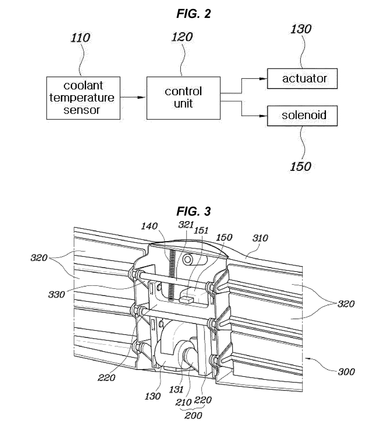
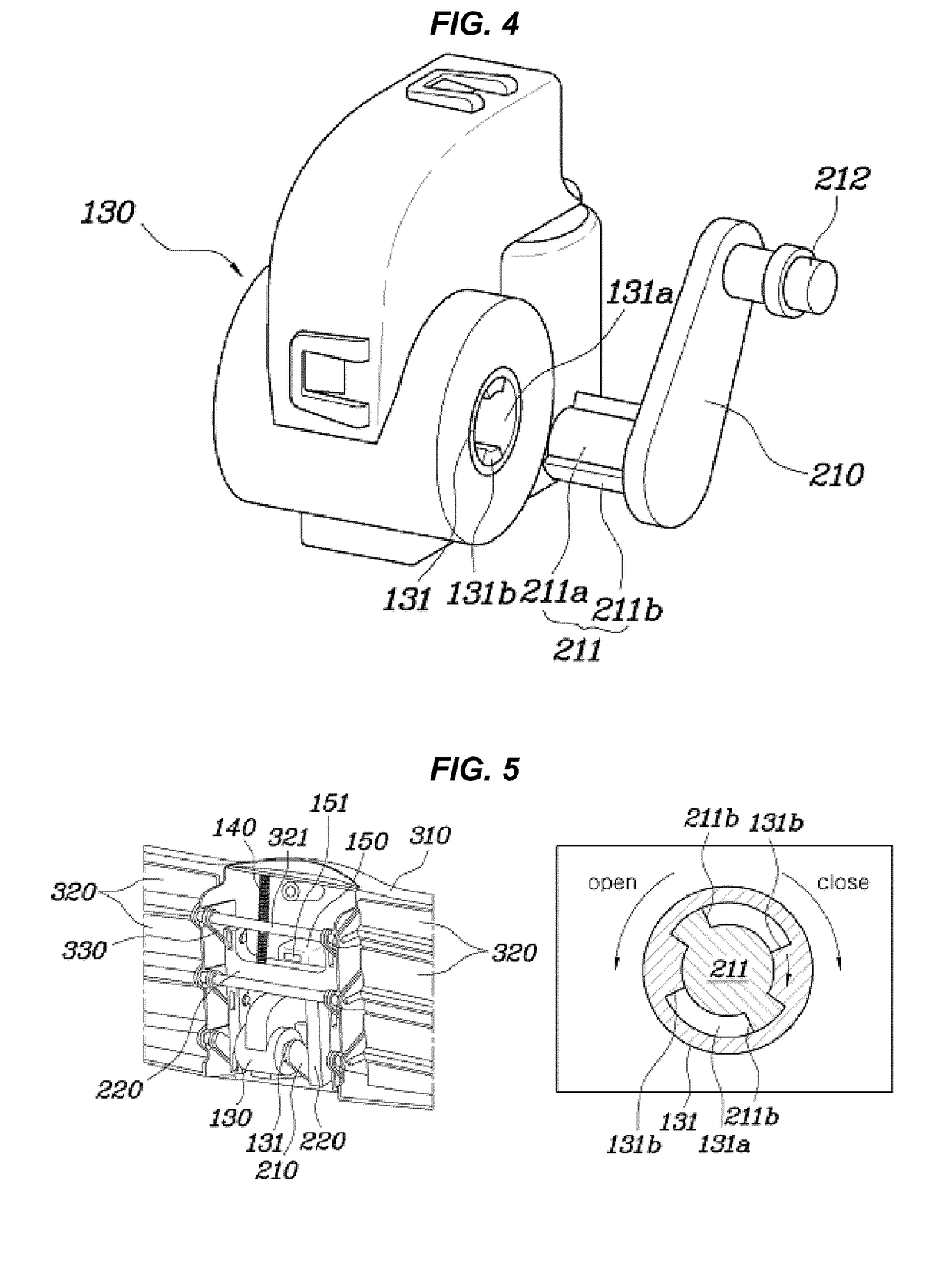
[0031]FIG. 2 is a block diagram illustrating the control of a fail-safe air flap control apparatus according to the present invention. FIG. 3 is a view showing the construction of the fail-safe air flap control apparatus according to the present invention.

[0032]As shown in FIGS. 2 and 3, the fail-safe air flap control apparatus for ve...


PUM


Abstract

A fail-safe air flap control apparatus for a vehicle includes a coolant temperature sensor, a control unit, an actuator, a movable unit, a flap unit, an elastic member and a solenoid unit. The coolant temperature sensor measures the temperature of a coolant. The control unit compares a value measured by the sensor to a reference value and generates a corresponding control signal. The actuator has a rotator which rotates in a clockwise or counterclockwise direction depending on the control signal. The movable unit linearly moves under rotational force of the rotator. The flap unit includes a flap housing having an air flow slot, a flap door mounted to the flap housing to openably close the air flow slot, and a connecting rod connected to the movable unit. The elastic member applies elastic force to the movable unit in a direction in which the flap door opens. The solenoid unit is controlled by the control signal of the control unit so as to either restrain movement of the movable unit and so maintain the flap door in a closed state or to release the movable unit.

Description

CROSS-REFERENCE TO RELATED APPLICATION[0001]The present application claims priority of Korean Patent Application Number 10-2009-0079684 filed on Aug. 27, 2009, the entire contents of which application is incorporated herein for all purposes by this reference.BACKGROUND OF THE INVENTION[0002]1. Field of the Invention[0003]The present invention relates to a fail-safe air flap control apparatus for a vehicle which is constructed so as to prevent an air flap from stopping in a closed state when malfunctioning[0004]2. Description of Related Art[0005]Generally, a water-cooled type engine cooling apparatus includes a water jacket, a water pump, a radiator, a fan and a thermostat. The water jacket surrounds the cylinders and combustion chamber of the engine. The water pump supplies water into the cylinders under pressure to circulate it around the cylinders. The radiator transfers heat of coolant, which has been heated, to the air. The fan assists the heat exchange of the radiator. The ther...

Claims


Application Information

Patent Timeline
Patent Type & Authority Patents(United States)
IPC IPC(8): B60K11/08
CPCF01P7/12F01P2031/00B60K11/085Y02T10/88B60K11/04B60H1/00B60K11/00
Inventor SHIN, YONG SUKKIM, HUN SOOJEONG, HEE JUNKIM, IN CHEOL
Owner HYUNDAI MOTOR CO LTD
Why Eureka
Try Eureka