
Compound barrier mechanism for passageway control

a barrier mechanism and passageway technology, applied in the field of barriers, can solve the problems of inefficient space use of the rotating leaf unit, damage to the space left below, and ineffective use of the space by the rotating leaf uni

Active Publication Date: 2012-03-06
HELLMAN SR ROBERT R +1
View PDF12 Cites 6 Cited by
  • Summary
  • Abstract
  • Description
  • Claims
  • Application Information

AI Technical Summary

Benefits of technology

[0020]It is yet an additional object of the invention to provide such a barrier mechanism that does not

Problems solved by technology

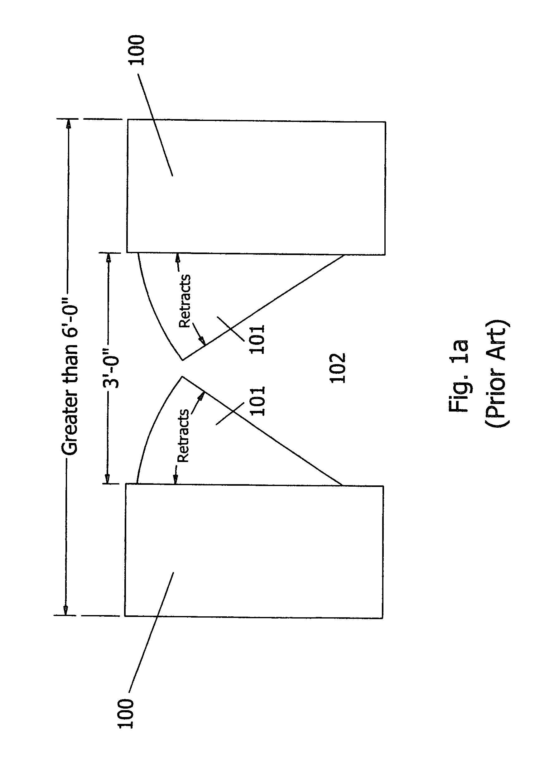
Disadvantages include an open wedge-shaped area below the leaves, of sufficient size such that when attempts are made to block larger passageways, the space left below is large enough to crawl through.
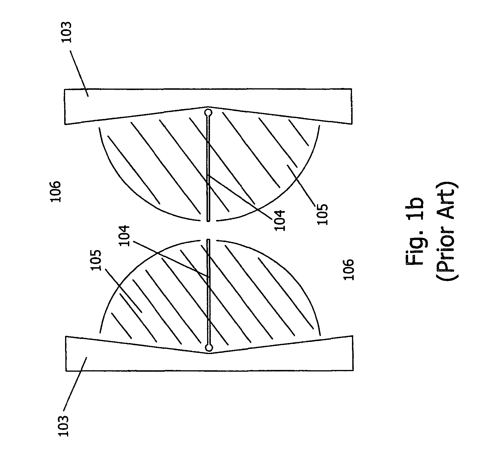
Another disadvantage is that the rotating leaf is difficult to support and therefore easy to deflect in the direction of passage, typically resulting in its damage.
Significantly, the rotating leaf unit is inefficient in its use of space in that the cabinet into which the leaf rotates must be at least as deep as the width of the leaf.
Lastly, if a pedestrian inadvertently contacts the leaves as they are nearly closed, the risk of injury is significant as their motion is 90 degrees to the direction of passage and it may be too late to drive them out of the way, resulting in pedestrian injury.
However, it is common that pedestrians in a two-way traffic situation are preoccupied or unwilling to wait their turn, and wind up walking into the edge of a panel or bar that is coming toward them.
Since the pivot axis is fixed, the usual outcome of contact is pedestrian injury.
Since the swinging panels require a significant portion of the lane to swing out of the way, it is common that a swinging panel will crash into the footrests on the wheelchair.
It has the inherent disadvantage of the leaf unit in that it is difficult to properly support the panels, particularly full height ones, without an unusually large cabinet.
There is a further issue that, when attempts are made to completely secure an entrance, these units require an additional fixed panel above the wide cabinet to preclude passage between two adjacent lanes.
Common to all of the above, based on customer feedback, is a distinct lack of reliability across the entire spectrum of existing panel or swing gate designs as manufactured by others.
Further common to all of the above, is the need, at times, for expensive additional fabrications to make up the difference between the outer dimension of the units and the inside dimensions of the hallway or entryway.
Since this involves attachment to the finished floor, or the finished wall, or the unit, at times of construction this can become an expensive last minute fabrication at considerable expense.
Yet another disadvantage of prior art devices is the difficulty, time, and expense associated with replacement of the unique glass panels, in the event of breakage.
Specialized tools and skills are also typically required, increasing costs to the end user.

Method used


Image

  • Compound barrier mechanism for passageway control
  • Compound barrier mechanism for passageway control
  • Compound barrier mechanism for passageway control

Examples


Embodiment Construction

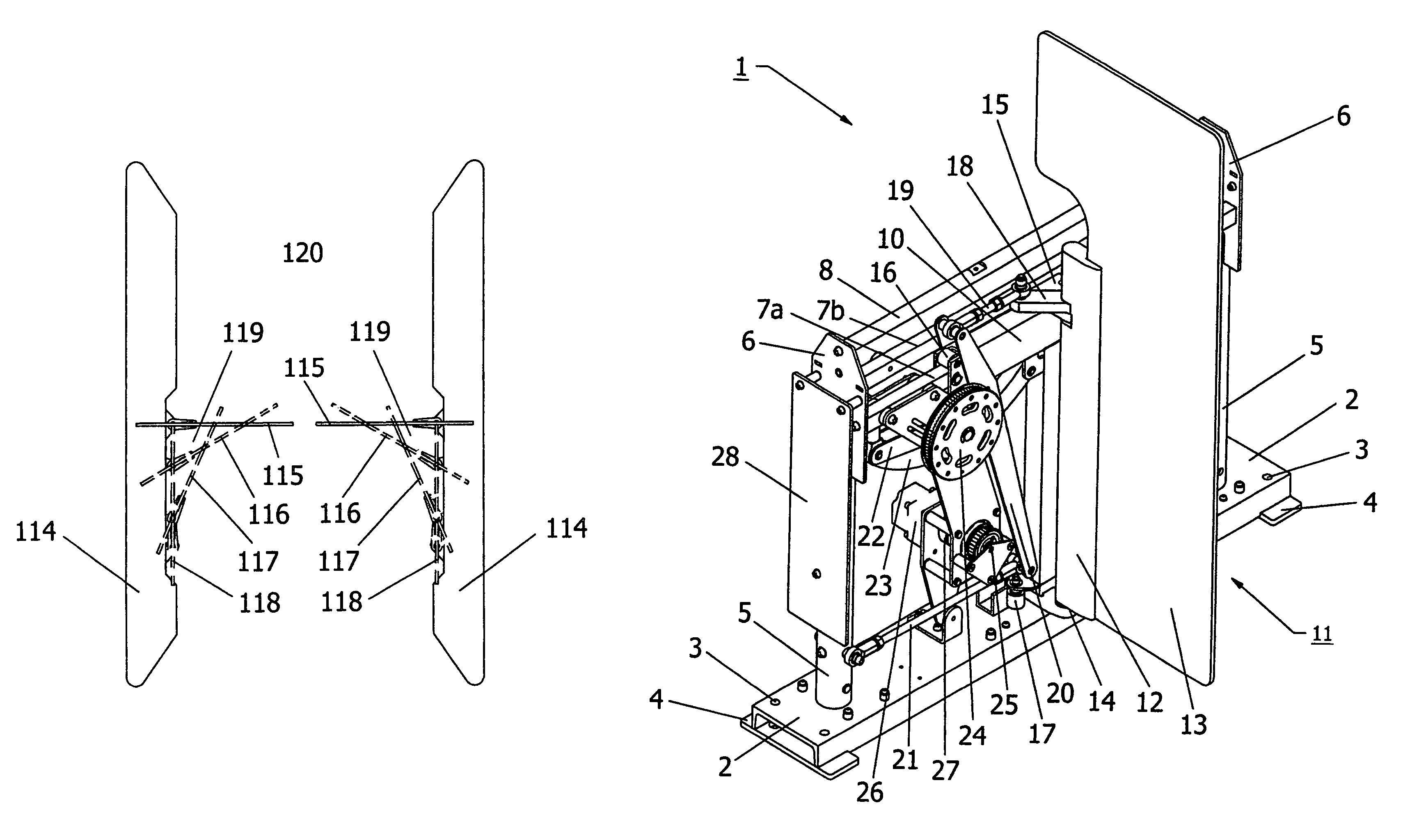
[0039]Reference should now be made to drawing FIGS. 2a-9, provided for purposes of illustration only, and on which the figure numerals in parentheses (when used) refer the reader to the figure in which the element(s) being described are more fully shown, although the element(s) may be shown on other figures also.

General

[0040]The invention is applicable to moving any substantially planar barrier, or panel, in that all advantages can apply whether the barrier is a series of vertical or horizontal bars affixed to a full or partial frame, or as in the initial target market, a glass pane of waist or full height.

[0041]In the case of a full height glass pane, the intent is to create an unattended entrance. It is further the intent to use the invention in tandem, such that an enclosed vestibule-type area, for observation and possible detention, can be created as a standalone product. This is desirable when the need to handle ADA traffic precludes the use of a revolving door or there is inad...


PUM


Abstract

A barrier mechanism for providing selective access to a passageway on the floor of a lobby, room or pavilion. It utilizes a frame and carriage assembly thereon, a panel which is swivelable to selectively overlie and block the passageway, and an electric motor which powers the carriage assembly and moves the panel. A group of power components, including a driver operated by the motor and other linkages on the frame, provide simultaneous translating movement of the carriage assembly and panel and swiveling of the panel, synchronized to bring about a “wrap-around” effect to the latter. Optionally, the panel can be locked in either its blocking or its access position. Important safety features are incorporated in the mechanism, to prevent inadvertent injury to passageway personnel.

Description

CROSS-REFERENCES TO RELATED APPLICATIONS[0001]The present application claims the benefit of the filing date of U.S. Provisional Application No. 60 / 737,211 filed Nov. 16, 2005, and titled COMPOUND BARRIER MECHANISM FOR PASSAGEWAY CONTROL AND METHOD OF USE, now abandoned.[0002]The present application is a continuation-in-part of our Utility application, U.S. Ser. No. 11 / 600,626 filed Nov. 16, 2006 now abandoned, and entitled COMPOUND BARRIER MECHANISM FOR PASSAGEWAY CONTROL, now abandoned.STATEMENT AS TO RIGHTS TO INVENTIONS MADE UNDER FEDERALLY-SPONSORED RESEARCH AND DEVELOPMENT[0003]Research and development of the present invention and application have not been Federally-sponsored, and no rights are given under any Federal program.BACKGROUND OF THE INVENTION[0004]1. Field of the Invention[0005]The present invention relates to barrier mechanisms generally and, more particularly, but not by way of limitation, to novel compound barrier mechanisms for passageway control.[0006]2. Backgr...

Claims


Application Information

Patent Timeline
IPC IPC(8): E01F13/00
CPCE06B11/085
Inventor HELLMAN, SR., ROBERT R.HELLMAN, JR., ROBERT R.
Owner HELLMAN SR ROBERT R
Learn More