
Intervertebral implant for lumbosacral joint

a technology for intervertebral implants and lumbosacral joints, which is applied in the field of intervertebral implants for lumbosacral joints, can solve the problems of inability to put a spacer of that type over the lumbosacral joint, implant is relatively bulky, and implant presents certain drawbacks, so as to simplify the actions of the surgeon

Inactive Publication Date: 2012-03-06
ZIMMER SPINE INC
View PDF19 Cites 30 Cited by
  • Summary
  • Abstract
  • Description
  • Claims
  • Application Information

AI Technical Summary

Benefits of technology

The invention provides an improved design that makes it easier for a surgeon to attach a bar to another object called a spacer during surgery. This attachment process involves adding a recess on the bottom of the spacer where the middle part of the bar can be snapped into place, which saves time and reduces complexity compared to previous methods.

Problems solved by technology

The technical problem addressed in this patent is how to create an intervertebral implant that can reduce pain caused by stress on the intervertebral disc between two vertebrae without causing damage to the sacroiliac joint (which consists of three vertebrae) at the level of the lumbo-sacral junction. Previous solutions involve placing a spacer in the area but there were limitations related to the structure of the sacrum and other factors like difficulty in placement within the patient's body.

Method used


Image

  • Intervertebral implant for lumbosacral joint
  • Intervertebral implant for lumbosacral joint
  • Intervertebral implant for lumbosacral joint

Examples


Embodiment Construction

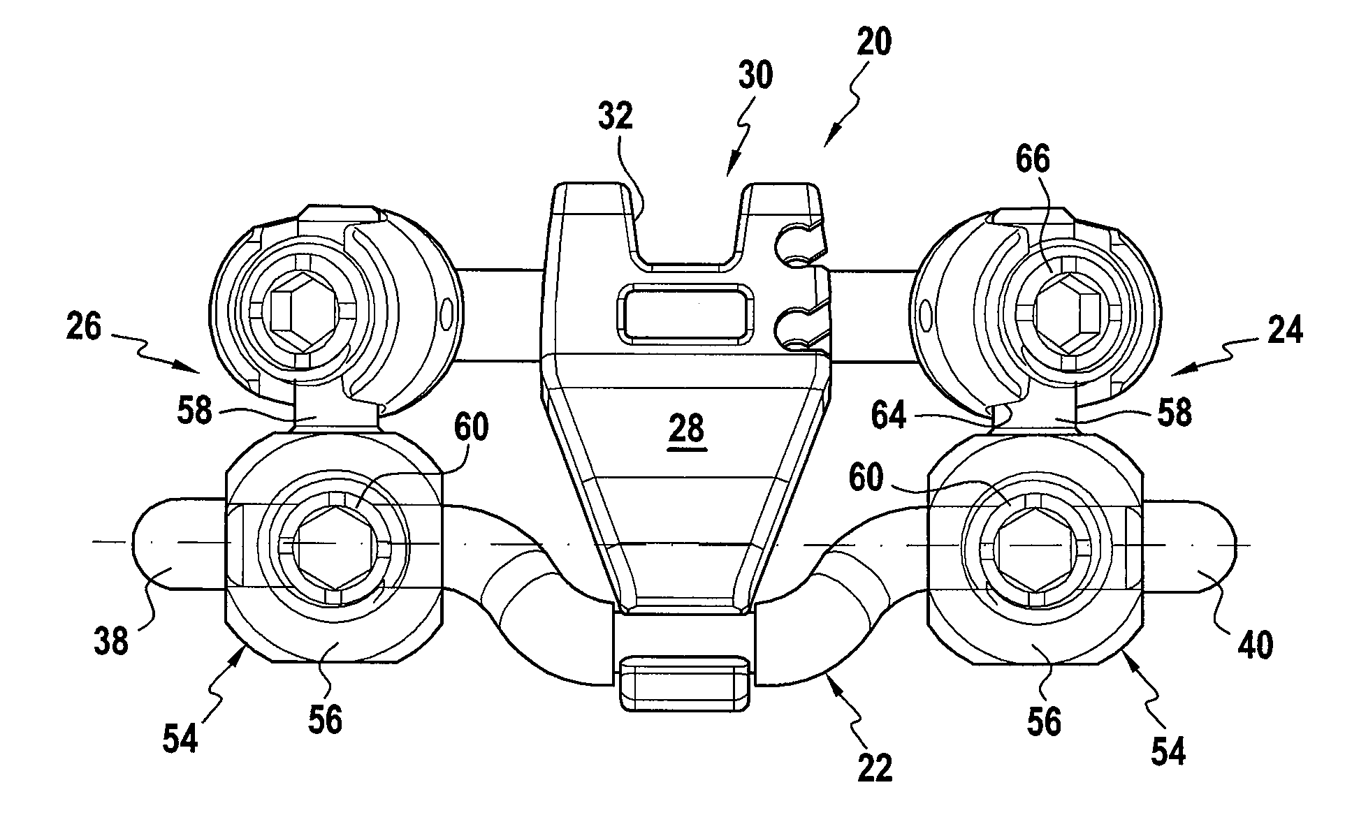
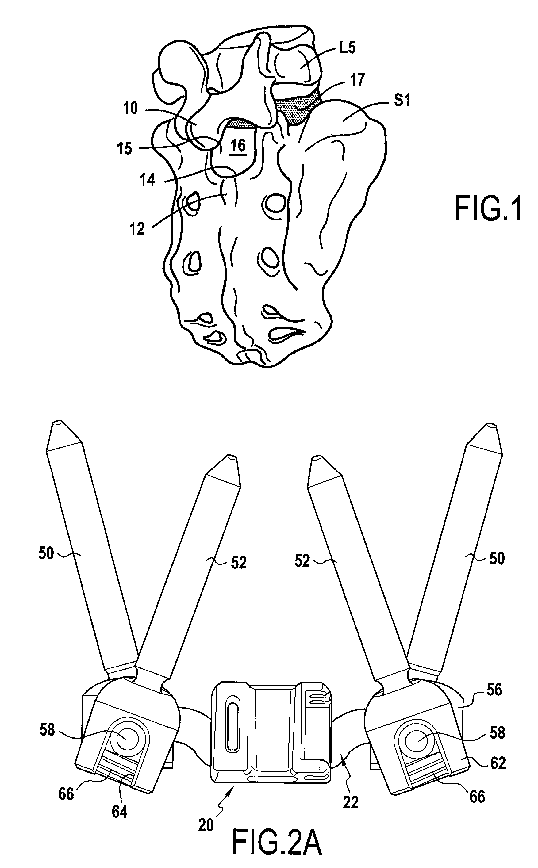
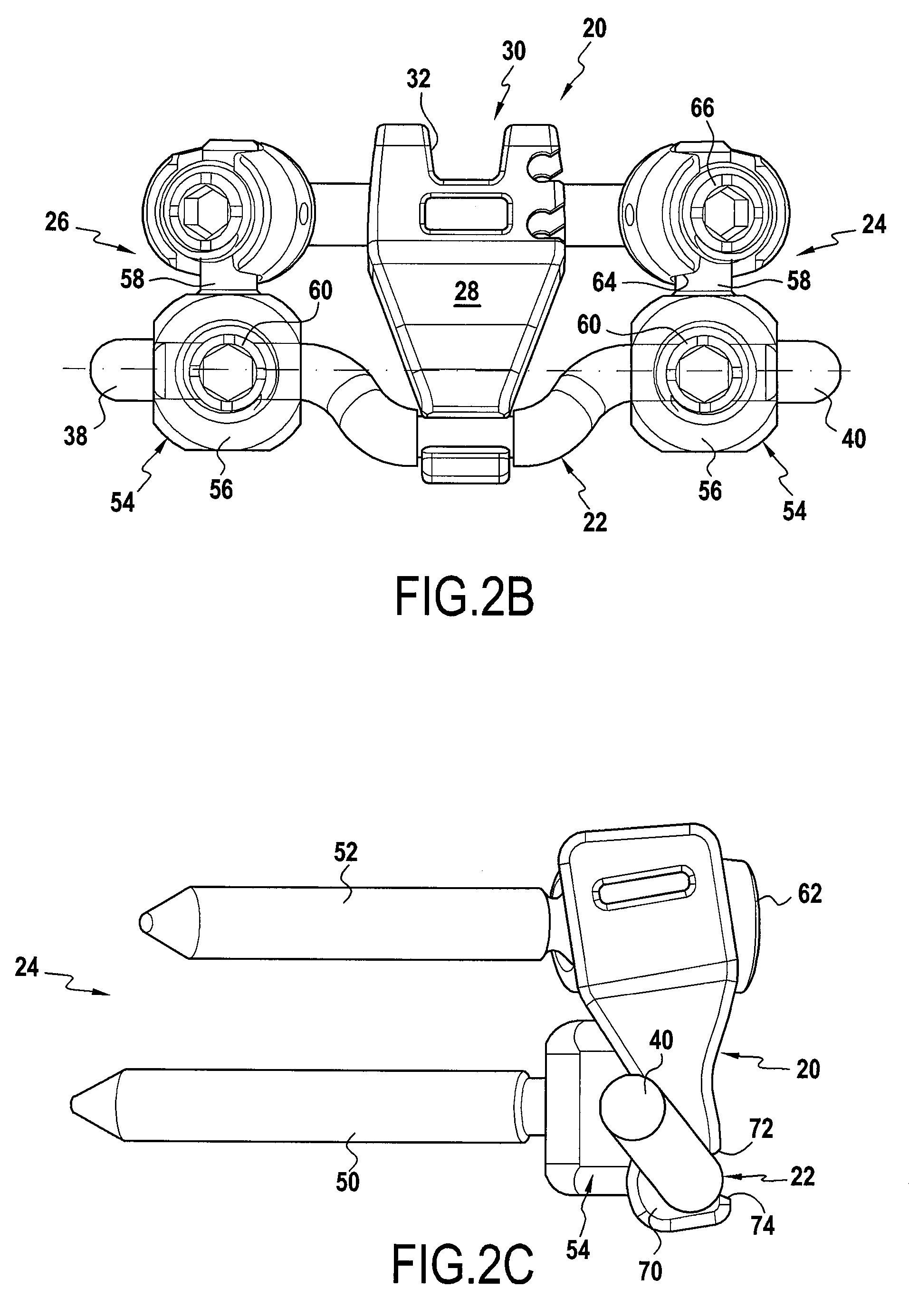
[0024]With reference initially to FIGS. 2A, 2B, and 2C, there follows a description of the component elements of the intervertebral implant for the lumbo-sacral joint.

[0025]The implant is constituted essentially by an intervertebral spacer 20, a connection bar 22, and two fastener systems 24 and 26 for fastening the connection bar 22 to the sacrum.

[0026]The spacer 20 comprises a body 28, a top end 30 of standard shape for an intervertebral spacer, i.e. provided with a recess 32 for receiving the spinous process 10 of the fifth lumbar vertebra, and a bottom end 34 for co-operating with the connection bar 22.

[0027]The connection bar 22 has a middle portion 36 that co-operates with the second end 34 of the intervertebral spacer 20, and two fastener ends 38 and 40 that co-operate with the respective fastener systems 24 and 26 in the sacrum.

[0028]With reference now to FIG. 5, there follows a more detailed description of a preferred embodiment of the connection bar 22 which constitutes an...


PUM


Abstract

The invention relates to an implant for placing between the sacrum of a patient and the fifth lumbar vertebra. It comprises a connection bar (22), fastener means (24, 26) for fastening each end of the connection bar to the sacrum, and a spacer (20) having a first end for co-operating with the spinous process of the fifth lumbar vertebra, and a second end for co-operating with said connection bar, the implant being characterized in that said connection bar (22) has two ends (38, 40) presenting a common first geometrical axis, and a middle portion (36) connected to said ends, said middle portion lying on a second geometrical axis parallel to the first geometrical axis but offset relative thereto, second end of the spacer co-operating with said middle portion.

Description


Claims


Application Information

Patent Timeline
Owner ZIMMER SPINE INC
Learn More