Light source control device

a control device and light source technology, applied in the direction of electronic switching, pulse technique, instruments, etc., can solve the problems of constant switching damage and wear of the switch, and achieve the effect of decreasing damage and wear

Inactive Publication Date: 2012-03-06
PRINCETON TECH CORP
View PDF2 Cites 0 Cited by
  • Summary
  • Abstract
  • Description
  • Claims
  • Application Information

AI Technical Summary

Benefits of technology

[0007]A light source control device for a light source is provided. A sensing device is disposed to add another input terminal to a light source, providing external control thereto which may be varied, thus decreasing damage and wear to a single switch which is used as an input terminal.
[0009]The light source control device of the invention decreases damage and wear to switches of electronic apparatuses. In the invention, the sensing device functions as an additional input terminal, such that two control operations “switching” and “powering on / off” are controlled by different input terminals, thus decreasing damage and wear to switches and increasing operating lifespan.

Problems solved by technology

However, with one switch, constant switching damages and wears the switch over time.

Method used


Image

  • Light source control device
  • Light source control device
  • Light source control device

Examples


Embodiment Construction

[0017]The following description is of the best-contemplated mode of carrying out the invention. This description is made for the purpose of illustrating the general principles of the invention and should not be taken in a limiting sense. The scope of the invention is best determined by reference to the appended claims.

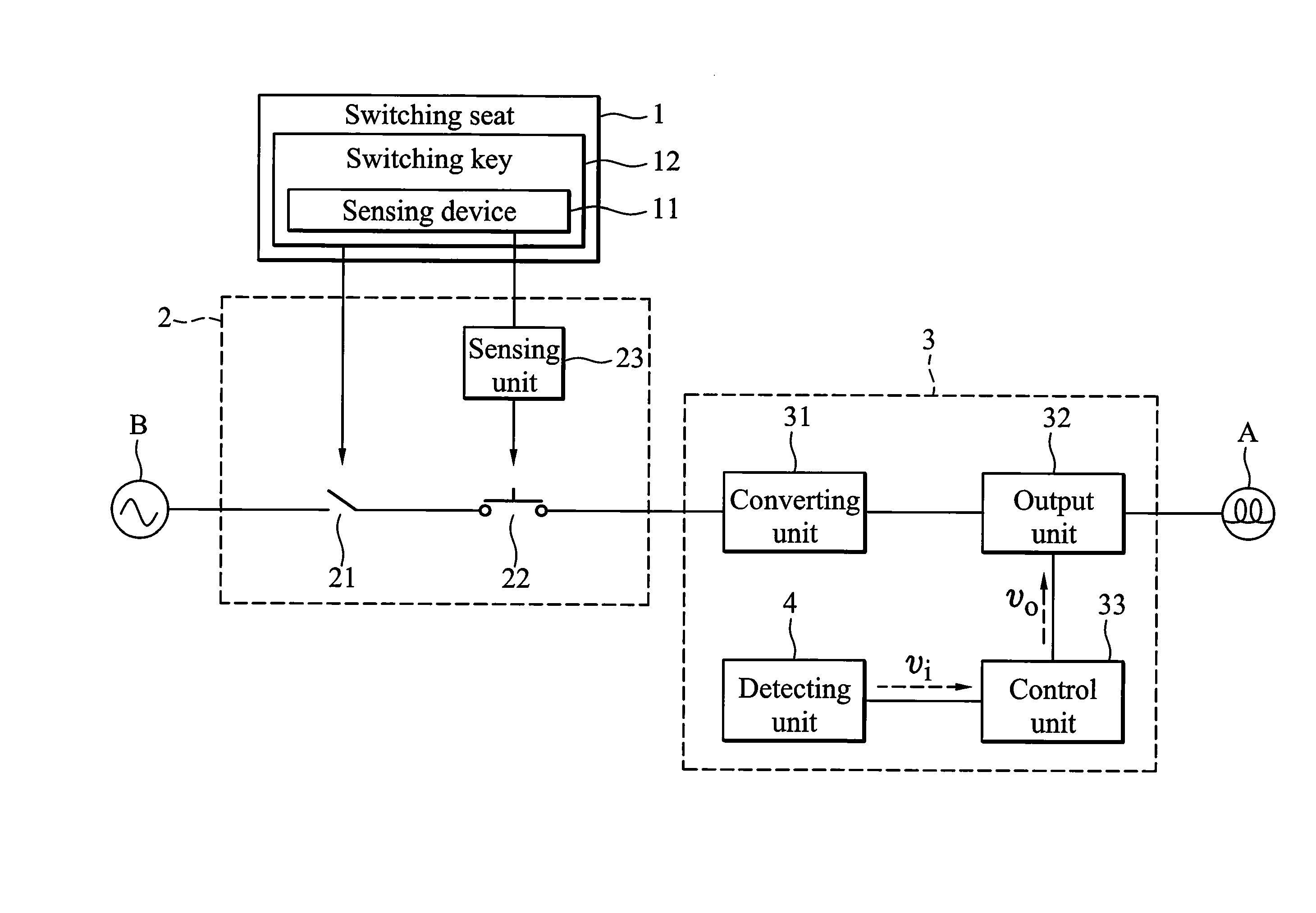
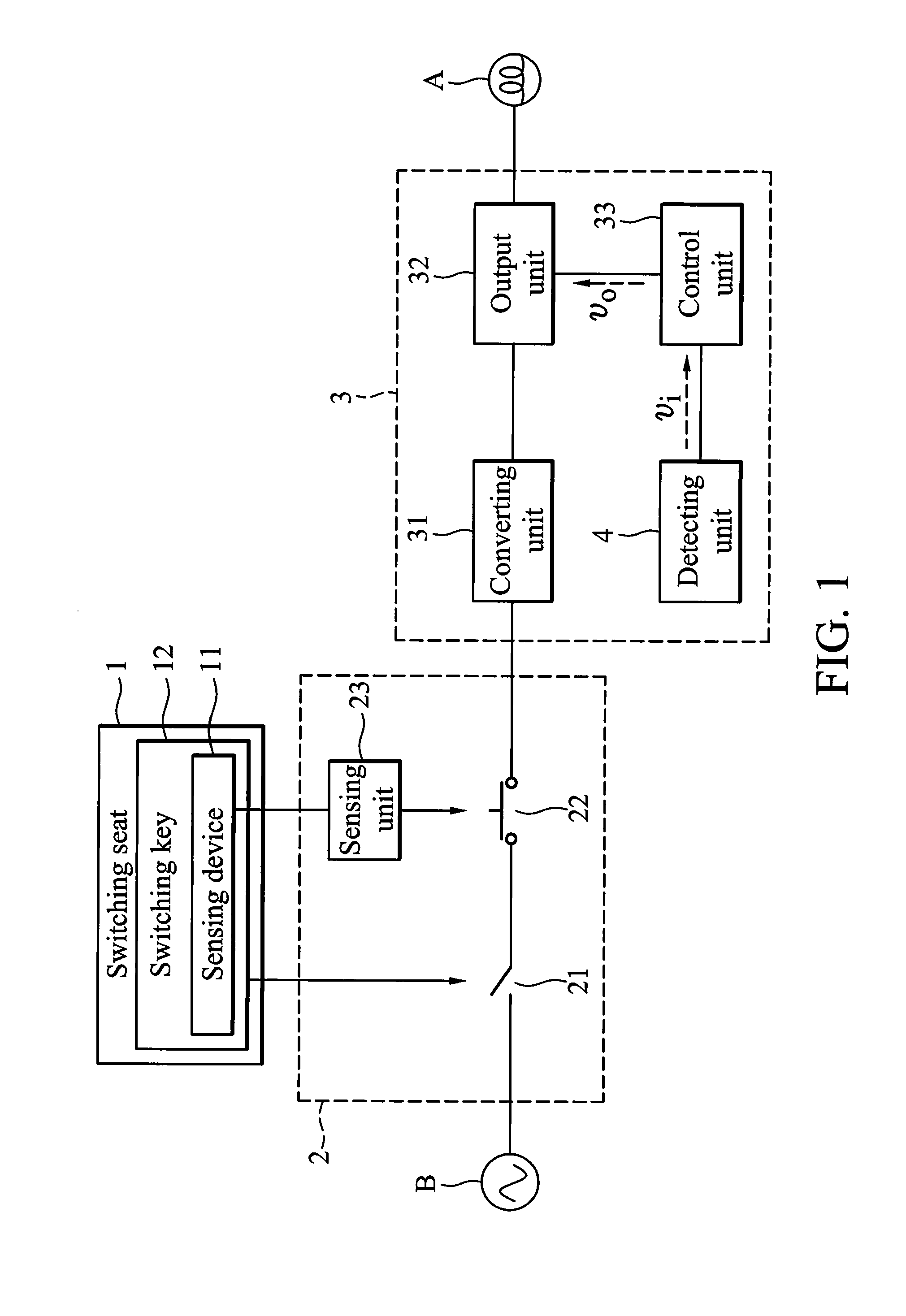
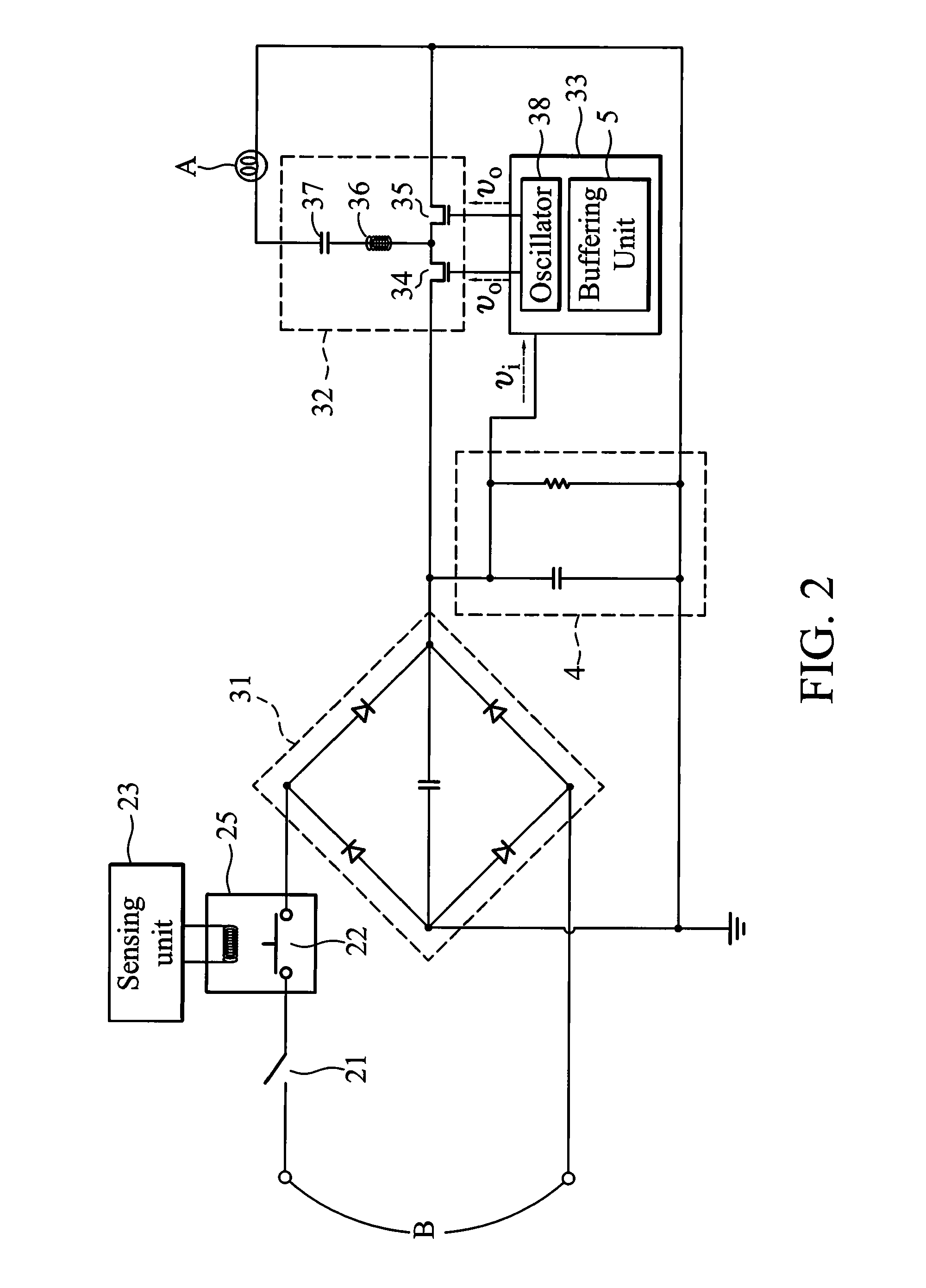
[0018]FIG. 1 to FIG. 4 show a light source control device for controlling a fluorescent lamp A according to an embodiment of the invention, wherein a power supplied to the fluorescent lamp A is a direct current (DC) power and an external power source B is an alternating current (AC) power. The light source control device comprises a switching seat 1, a switching circuit 2 and a control circuit 3.

[0019]The switching seat 1 comprises a sensing device 11 and a switching key 12. The sensing device 11 is a capacitor type object sensor comprising a capacitor which is composed of two flat plates PA and PB, as shown in FIG. 3. A dielectric material is disposed between the flat...


PUM


Abstract

A light source control device is provided. A switching seat includes a switching key and a sensing device. A switching circuit is disposed between an external power source and a control circuit to disconnect or connect the external power source, and includes a mechanical switch, an electronic switch and a sensing unit. The mechanical switch is directly connected to the switching key, and is controlled to turn on or off by switching the switching key. The electronic switch is coupled to the sensing unit, and the sensing unit generates a sensing signal to control the electronic switch to turn on or off when the sensing device senses an excitation. The control circuit provides varied power supply to a light source according to the received signal.

Description

CROSS REFERENCE TO RELATED APPLICATIONS[0001]This Application claims priority of Taiwan Patent Application No. 097223949, filed on Dec. 31, 2008, the entirety of which is incorporated by reference herein.BACKGROUND OF THE INVENTION[0002]1. Field of the Invention[0003]The invention relates to a light source control device, and more particularly to a light source control device with a mechanical switch and an electronic switch.[0004]2. Description of the Related Art[0005]Electronic apparatuses, such as lamps, fans and so on, do not need complex manipulation. Therefore, a simple switch and a control integrate circuit (IC) are used to control the electronic apparatuses in order to simplify structure and increase manipulate conveniently. The switch is used as a single input terminal that can provide external control which may be varied to provide various operation models according to switching number of the switch correspondingly.[0006]However, with one switch, constant switching damages...

Claims


Application Information

Patent Timeline
Patent Type & Authority Patents(United States)
IPC IPC(8): H05B37/02
CPCH05B37/0227H03K17/962H05B47/105
Inventor KUO, FU-RUNG
Owner PRINCETON TECH CORP
Why Eureka
Try Eureka