Monitor apparatus

a technology for monitoring equipment and monitors, applied in the field of monitoring equipment, can solve the problems of reducing the life affecting the operation of the driving section, and being susceptible to external forces, so as to reduce the damage and wear of the driving section

Active Publication Date: 2012-03-06
ALPINE ELECTRONICS INC
View PDF12 Cites 2 Cited by
  • Summary
  • Abstract
  • Description
  • Claims
  • Application Information

AI Technical Summary

Benefits of technology

[0011]The present invention has been made in view of such drawbacks of the related art, and an object of the present invention is to provide a long-life monitor apparatus by reducing damage and wear of the driving section thereof

Problems solved by technology

However, when the display panel of the known monitor apparatus is in the upright position, it is susceptible to an external force, such as a force due to a passengerTs inadvertent contact, or a force intentionally induced by pushing or pulling down when the passenger operates an air-conditioner operation switch located behind the display panel or when the passenger adjusts the angle of the display panel to an easy-to-view position.
Since such an external force is transmitted to the driving section through the display panel, the driving section may be damaged and the life of the driving section may be reduced.
Since the driving section includes the gear transmission mechanism, a high load due to an external force applied to the display panel is applied to the gears of the gear transmission mechanism, which may thus cause loss of gear teeth, increase gear wear, and shorten the life of the gear transmission mechanism.
In this case, when the slipping section is in operation, a continuous high load due to an external force is repeatedly applied to the gear transmission mechanism to thereby increase gear wear and to shorten the life of the gear transmission mechanism.
In addition, the repeated slip operation of the slipping section increases the wear on components constituting the slipping section, thereby reducing a transmissible torque, inhibiting the gear transmission, and increasing the play in the entire gear train.
This makes it difficult to smoothly perform the pivoting operation of the display panel.
Additionally, since the display panel receiving an external force is maintained at its position, there is a problem in that it is difficult to view the screen of the display panel.

Method used


Image

  • Monitor apparatus
  • Monitor apparatus
  • Monitor apparatus

Examples


Embodiment Construction

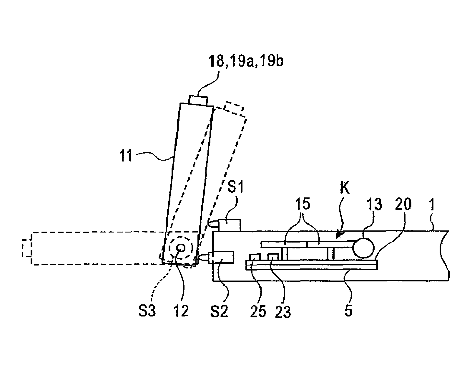
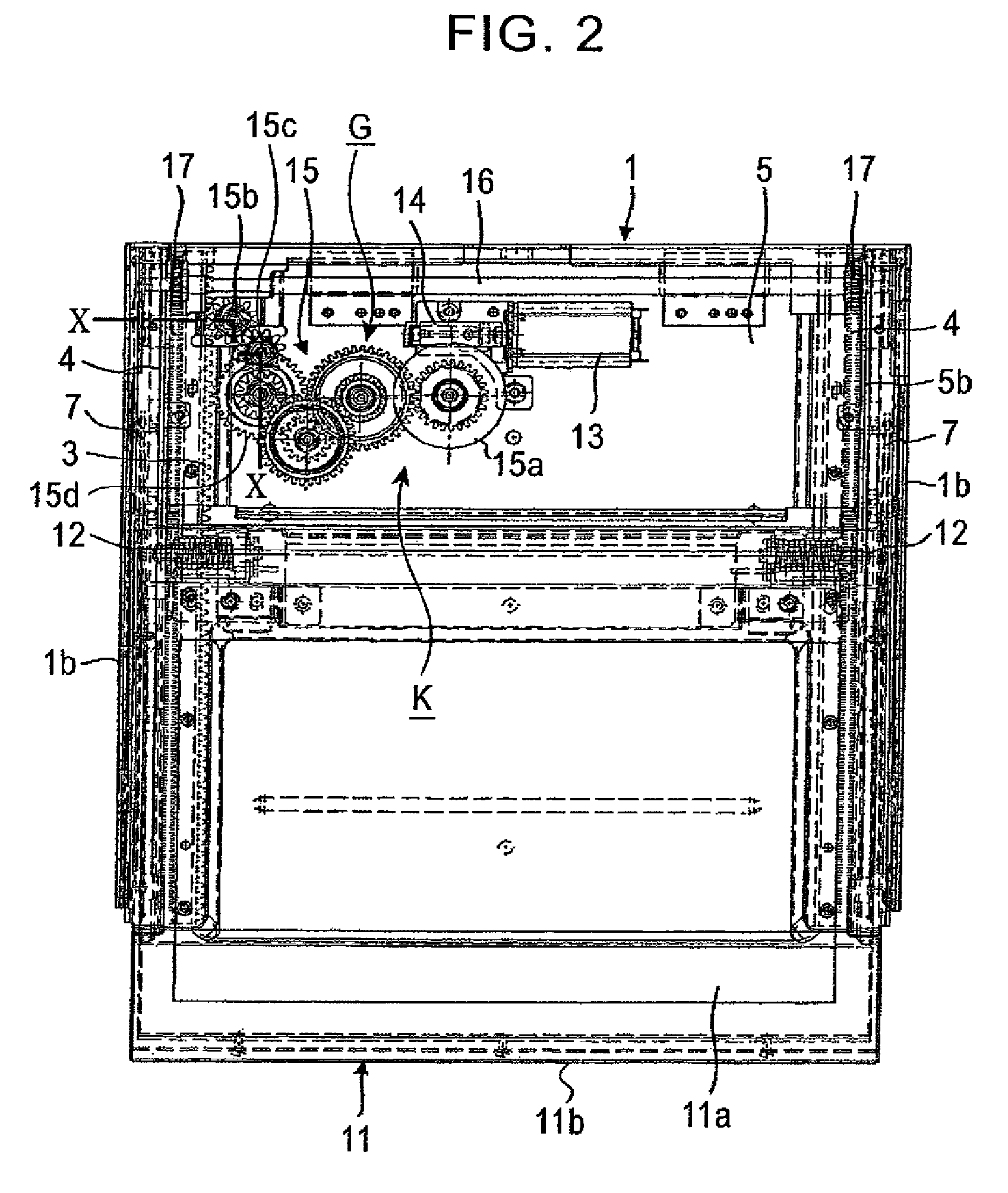
[0051]The configuration and the operation of a monitor apparatus according to one embodiment of the present invention will now be described with reference to FIGS. 1 to 7. The monitor apparatus of the present invention generally includes a housing 1, a slide body 5 movably attached to the housing 1, a drive source 13 attached to the slide body 5, a gear transmission mechanism G meshed with the drive source 13, a clutching section (clutching means) 32 (FIG. 10) provided for one of the gear transmission mechanism G, a detecting section (detecting means) 21 (FIG. 11) provided for one gear of the gear transmission mechanism G, a display panel 11 pivotably attached to the slide body 5, and a driving section (driving means) K for driving the display panel 11.

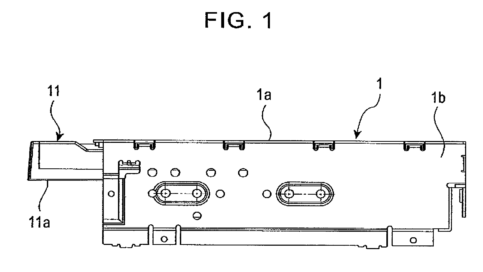
[0052]The housing 1 is accommodated in the dashboard of a vehicle and the front side (the left-hand side in FIG. 1) of the housing 1 is open. The housing 1 includes an upper flat plate 1a, a pair of opposing side plates 1b that are be...


PUM


Abstract

A monitor apparatus includes a display panel housed in a housed position, a driving section, a detecting section, and a controlling section. The driving section includes a gear transmission mechanism for driving the display panel and causes the display panel to perform a first operation in which the display panel is moved from the housed position to an upright position via a horizontal position and a second operation in which the display panel is lowered from the upright position and is drawn into the housed position via the horizontal position. The detecting section detects when an external force is applied to the display panel placed in the upright position. When the detecting section detects that an external force is applied, the controlling section causes the driving section to drive the display panel in a direction in which the external force was applied.

Description

RELATED APPLICATIONS[0001]The present application claims priority to Japanese Patent Application Number 2006-014047, filed Jan. 23, 2006, the entirety of which is hereby incorporated by reference.BACKGROUND[0002]1. Technical Field[0003]The present invention relates to a monitor apparatus mounted in a vehicle to display television programs, vehicle-travel information, and so on.[0004]2. Background Information[0005]Conventionally, monitor apparatuses for television or the like are accommodated in the dashboards of vehicles so that passengers can view the display portions (i.e., the screens) of the display panels. Such a known monitor apparatus has a housing installed in the vehicle dashboard, a slide body housed in the housing so that it can advance and retract, and a display panel pivotably attached to the slide body by using one end portion of the display panel as a pivot supporting point. The display panel can be shifted between a housed position in which the display panel is house...

Claims


Application Information

Patent Timeline
Patent Type & Authority Patents(United States)
IPC IPC(8): H04N5/64
CPCB60K35/00B60R11/0235B60K2350/405B60K2370/67
Inventor SANO, NORIYUKIKATSUNUMA, HIDETOENDO, NAOTOSHI
Owner ALPINE ELECTRONICS INC
Why Eureka
Try Eureka