Non-rotating pick with a pressed in carbide segment
What is AI technical title?
AI technical title is built by PatSnap AI team. It summarizes the technical point description of the patent document.
a technology of carbide segment and non-rotating pick, which is applied in the field of non-rotating pick, can solve the problems of wear on the attack tool, and achieve the effect of high impact resistan
Active Publication Date: 2012-03-20
SCHLUMBERGER TECH CORP
View PDF111 Cites 60 Cited by
Summary
Abstract
Description
Claims
Application Information
AI Technical Summary
This helps you quickly interpret patents by identifying the three key elements:
Problems solved by technology
Method used
Benefits of technology
Problems solved by technology
Formation degradation, such as asphalt milling, mining, or excavating, may result in wear on attack tools.
Method used
Image
Click on the blue label to locate the original text in one second.
Reading with bidirectional positioning of images and text.
Examples
Embodiment Construction
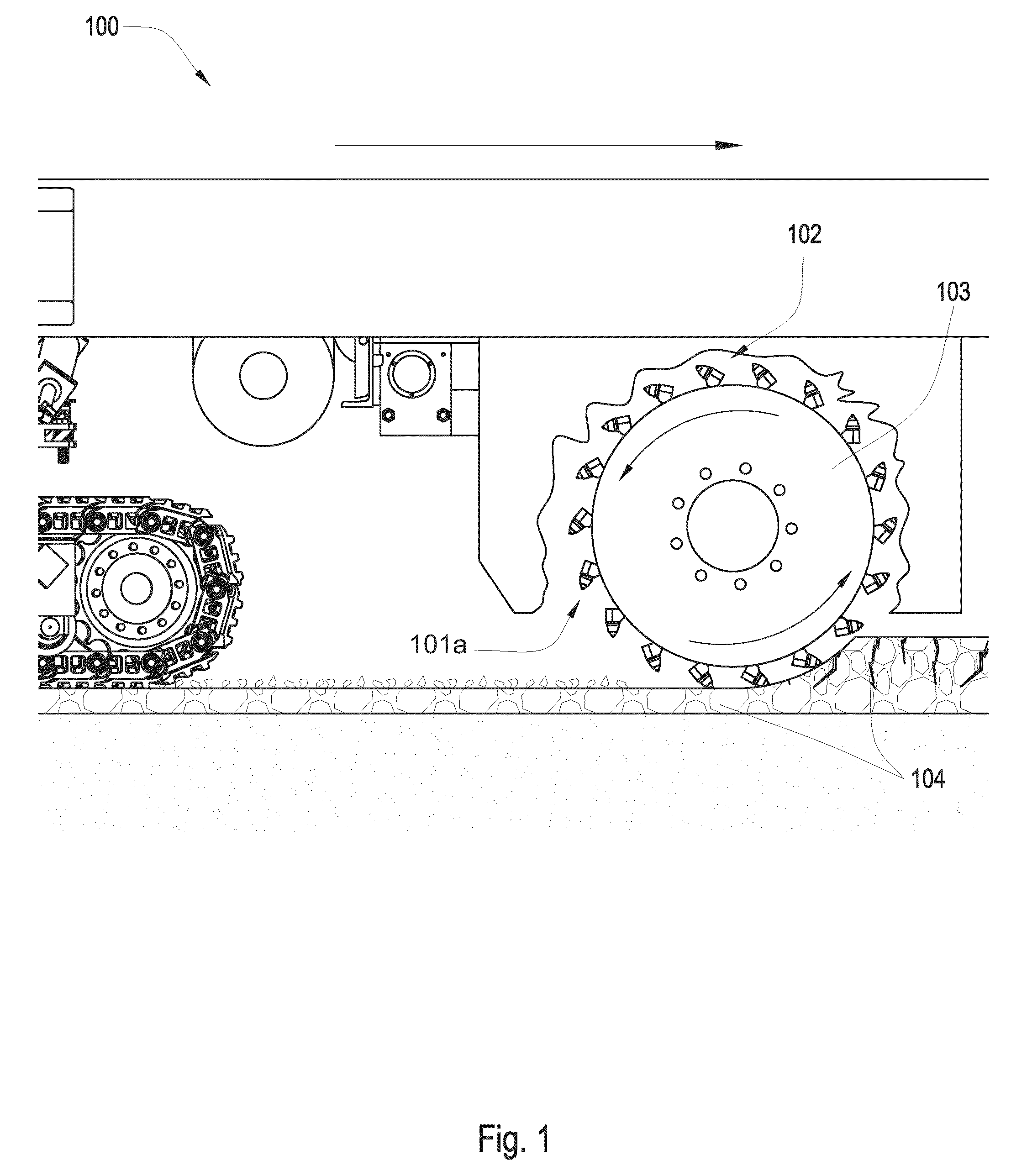
[0019]FIG. 1 is a cross-sectional diagram of an embodiment of a plurality of tools 101a attached to a rotating drum 103 connected to the underside of a pavement recycling machine 100. The recycling machine 100 may be a cold planer used to degrade man-made formations 104 such as pavement. Tools 101a may be rotationally fixed to the drum 103 bringing the tools 101a into contact with the formation 104. A holder 102 or block is attached to the rotating drum 103, and the tool 101a is inserted into the holder 102. The holder 102 or block may hold the tool 101a at an angel offset from the direction of rotation, such that the tool 101a engages the pavement at a preferential angle. The tool 101a may be rotationally fixed to the rotating drum 103.
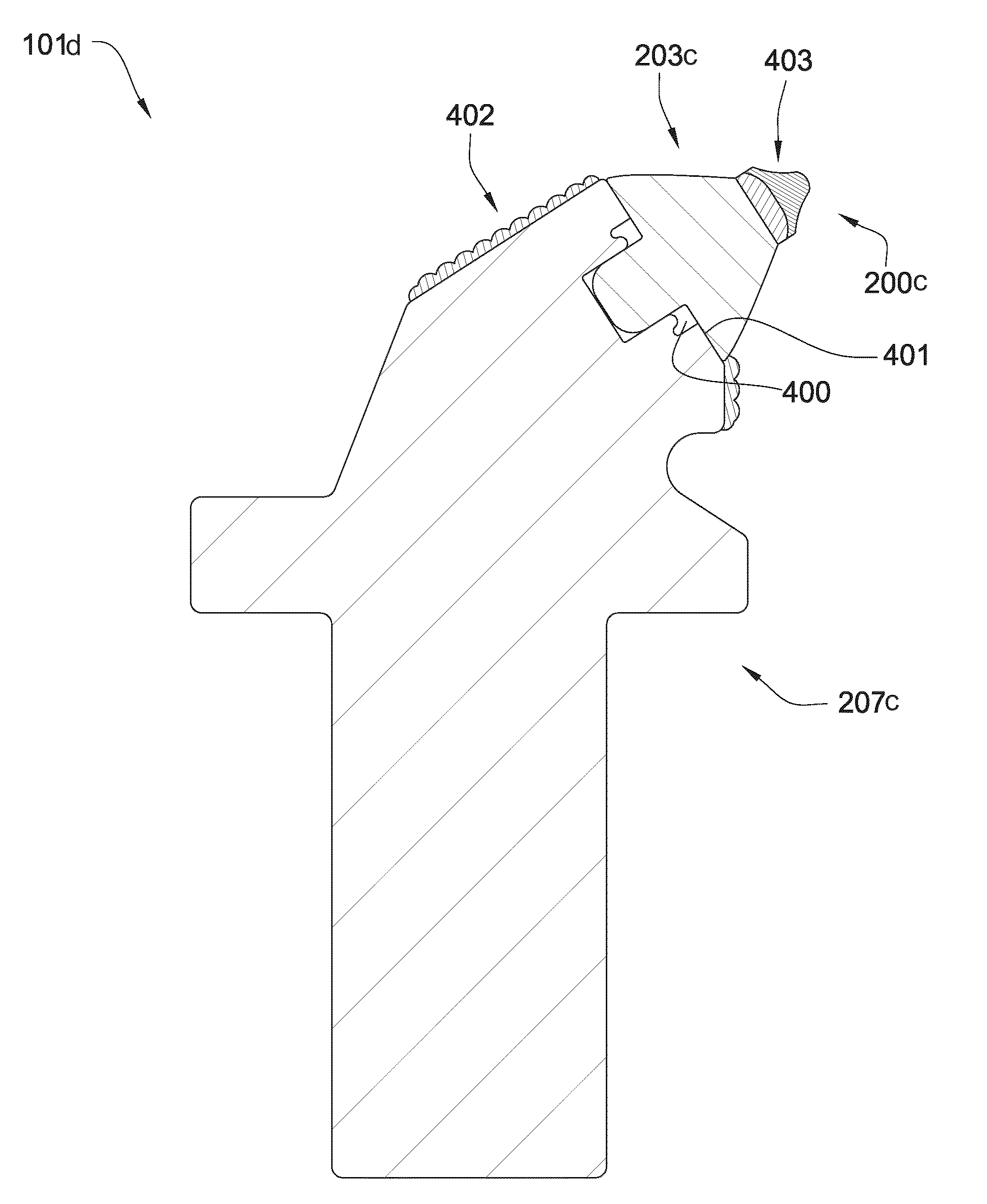
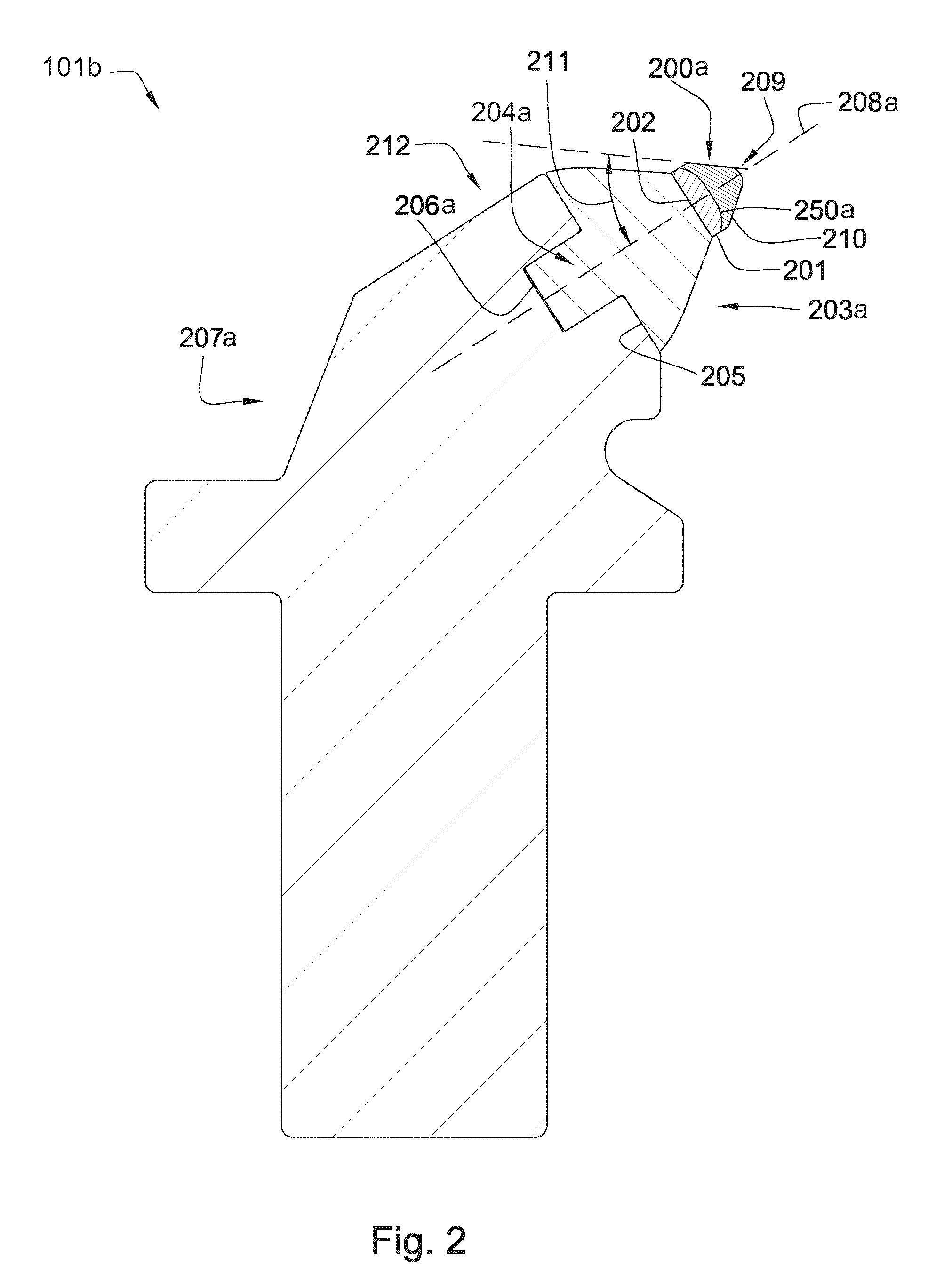
[0020]FIG. 2 illustrates a tool 101b having a superhard material 200a bonded to a cemented metal carbide substrate 201 at a non-planar interface 250a. The cemented metal carbide substrate 201 is bonded to a front end 202 of a cemented metal carbide s...
PUM
Property
Measurement
Unit
angle
aaaaa
aaaaa
thickness
aaaaa
aaaaa
angle
aaaaa
aaaaa
Abstract
In one aspect of the present invention, a high impact resistant tool has a superhard material bonded to a cemented metal carbide substrate at a non-planar interface. The cemented metal carbide substrate is bonded to a front end of a cemented metal carbide segment. A stem formed in the base end of the carbide segment opposite the front end is press fit into a bore of a steel body. The steel body is rotationally fixed to a drum adapted to rotate about its axis.
Description
CROSS REFERENCE TO RELATED APPLICATIONS[0001]This application is a continuation-in-part of U.S. patent application Ser. No. 11 / 871,722 filed on Oct. 12, 2007 and entitled “Hollow Pick Shank,” which issued Aug. 9, 2011 as U.S. Pat. No. 7,992,945. U.S. patent application Ser. No. 11 / 871,722 is a continuation-in-part of U.S. patent application Ser. No. 11 / 844,586 filed on Aug. 24, 2007 and entitled “Pick Assembly”, which issued Oct. 13, 2009 as U.S. Pat No. 7,600,823. U.S. patent application Ser. No. 11 / 844,586 is a continuation-in-part of U.S. patent application Ser. No. 11 / 829,761 on Jul. 27, 2007 and entitled “Pick Shank In Axial Tension”, which issued May 25, 2010 as U.S. Pat. No. 7,722,127.U.S. patent application Ser. No. 11 / 829,761 is a continuation in-part of U.S. patent application Ser. No. 11 / 773,271 filed on Jul. 3, 2007 and entitled “Tapered Bore In A Pick,” which issued Aug. 16, 2011 as U.S. Pat. No. 7,997,661. U.S. patent application Ser. No. 11 / 773,271 is a continuation-i...
Claims
Application Information
Patent Timeline
Application Date:The date an application was filed.
Publication Date:The date a patent or application was officially published.
First Publication Date:The earliest publication date of a patent with the same application number.
Issue Date:Publication date of the patent grant document.
PCT Entry Date:The Entry date of PCT National Phase.
Estimated Expiry Date:The statutory expiry date of a patent right according to the Patent Law, and it is the longest term of protection that the patent right can achieve without the termination of the patent right due to other reasons(Term extension factor has been taken into account ).
Invalid Date:Actual expiry date is based on effective date or publication date of legal transaction data of invalid patent.

