Cutting Tool

a cutting tool and tool body technology, applied in the field of cutting tools, can solve the problems of cutting tools that can experience wear in a number of ways

Inactive Publication Date: 2012-09-27
KENNAMETAL INC
View PDF13 Cites 37 Cited by
  • Summary
  • Abstract
  • Description
  • Claims
  • Application Information

AI Technical Summary

Benefits of technology

[0009]These and other aspects of the present invention will be more fully understood following a review of this specification and drawings.

Problems solved by technology

Cutting tools can experience wear in a number of ways due to the environment in which they operate and must be frequently replaced.

Method used


Image

  • Cutting Tool
  • Cutting Tool
  • Cutting Tool

Examples


Embodiment Construction

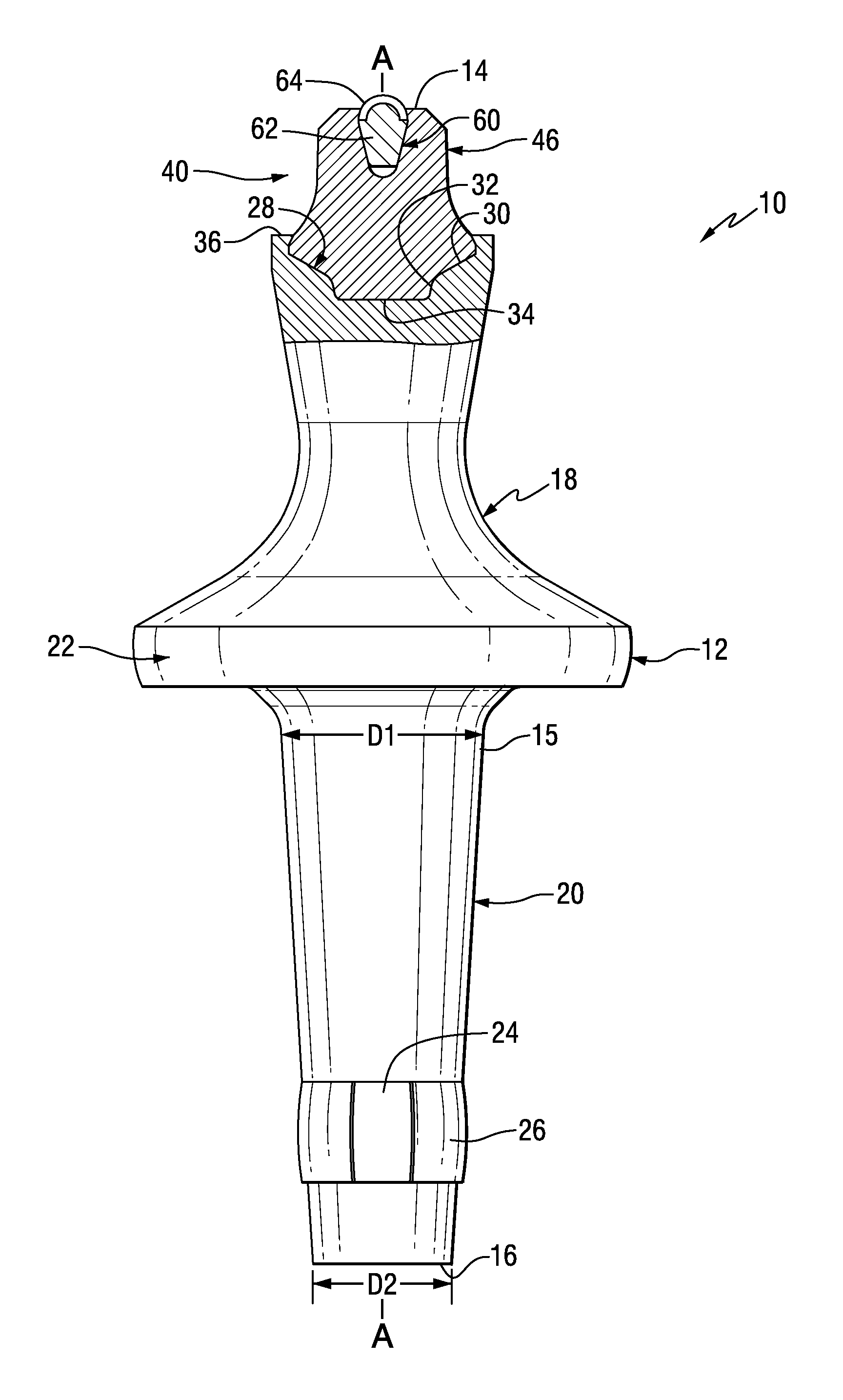
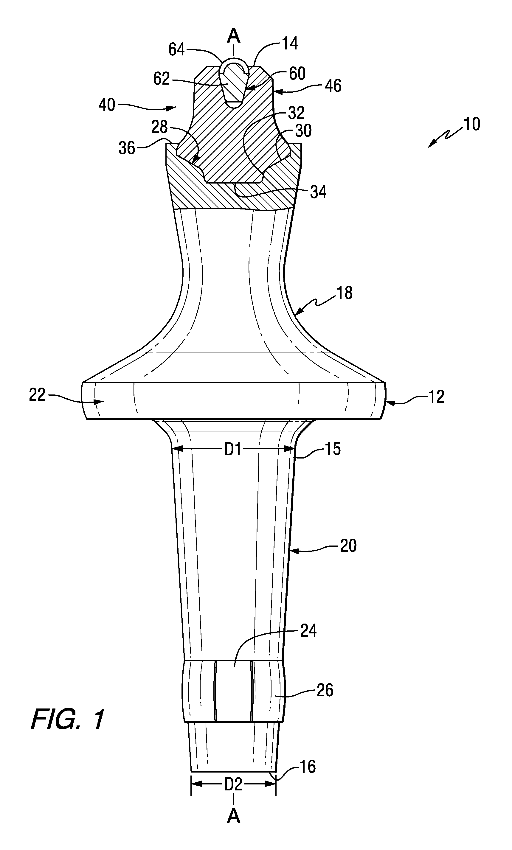
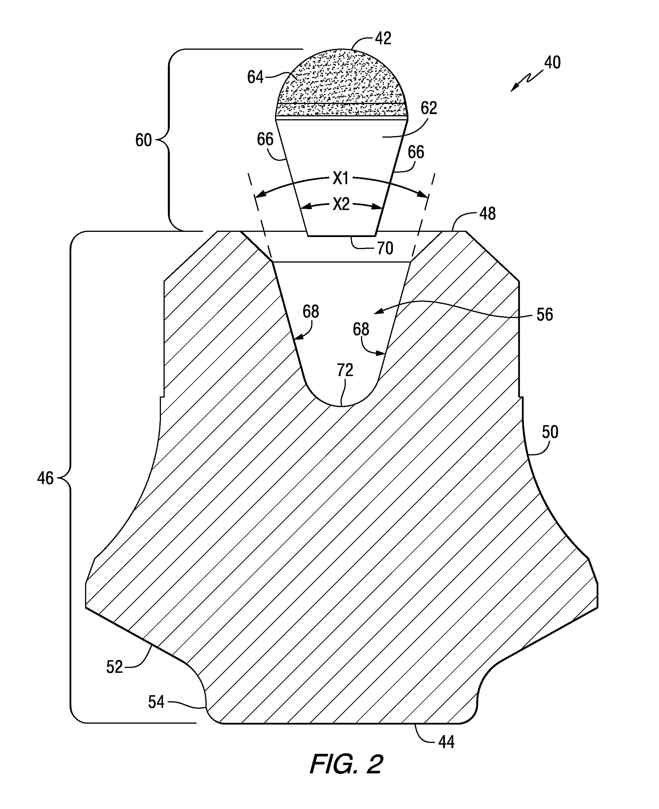
[0012]Referring to the drawings, FIGS. 1-2 illustrate a cutting tool of the invention, generally designated as 10. In one aspect, the invention illustrated herein pertains generally to road planing tools. However, one should appreciate that the invention has application to other kinds of cutting tools useful in other kinds of cutting operations. Exemplary operations include without limitation road planing (or milling), coal mining, concrete cutting, and other kinds of cutting operations wherein a cutting tool with a hard cutting member impinges against a substrate (e.g., earth strata, pavement, asphaltic highway material, concrete, and the like) breaking the substrate into pieces of a variety of sizes including larger-size pieces or chunks and smaller-sized pieces including dust-like particles. In addition, it will be appreciated that the cutting tool 10 of the invention may be manufactured in various sizes and dimensions depending upon the desired application of the tool.

[0013]As u...


PUM


Abstract

A cutting tool for use in impinging earth strata includes a cutting tool body having a head portion at an axial forward end, a collar portion axially rearward of the head portion, and a shank portion axially rearward of the collar portion at an axial rearward end, wherein the cutting tool body contains a first socket at the axial forward end thereof. The shank portion generally tapers in the axial rearward direction. The cutting tool also includes a hard cutting member affixed to the cutting tool body within the first socket. The hard cutting member includes an axial forward end and an axial rearward end. The hard cutting member also includes a superhard axial forward portion of the axial forward end thereof, wherein the superhard axial forward portion comprises a substrate and a layer of superhard material adhered to the substrate.

Description

CROSS-REFERENCE TO RELATED APPLICATIONS[0001]This application claims the benefit of U.S. Provisional Application No. 61 / 454,661 filed Mar. 21, 2011, which is hereby fully incorporated by reference.BACKGROUND OF THE INVENTION[0002]The invention pertains generally to a cutting tool that is useful for the impingement of a substrate or earth strata such as, for example, asphaltic roadway material, coal deposits, mineral formations and the like. More specifically, the invention pertains to the aforementioned cutting tool wherein the cutting tool, which may be either rotatable about its central longitudinal axis or an indexable type cutting tool that is symmetrical about its central longitudinal axis, carries a hard cutting member or a superhard cutting member at the axially forward end thereof. The superhard cutting member can be made from a superhard material (or includes a portion there of made from a superhard material). Superhard materials useful in the present invention include, wit...

Claims


Application Information

Patent Timeline
Patent Type & Authority Applications(United States)
IPC IPC(8): E21C35/183E21C35/18
CPCE21C35/183E21C35/18
Inventor OJANEN, RANDALL WALTER
Owner KENNAMETAL INC
Why Eureka
Try Eureka