

Pick with carbide cap
a technology of carbide cap and pick, which is applied in the direction of drilling accessories, cutting machines, cutting machines, etc., can solve the problems of wear and tear of attack tools, and achieve the effect of prolonging the life of the pick
- Summary
- Abstract
- Description
- Claims
- Application Information
AI Technical Summary
Benefits of technology
Problems solved by technology
Method used
Image

Examples
Embodiment Construction
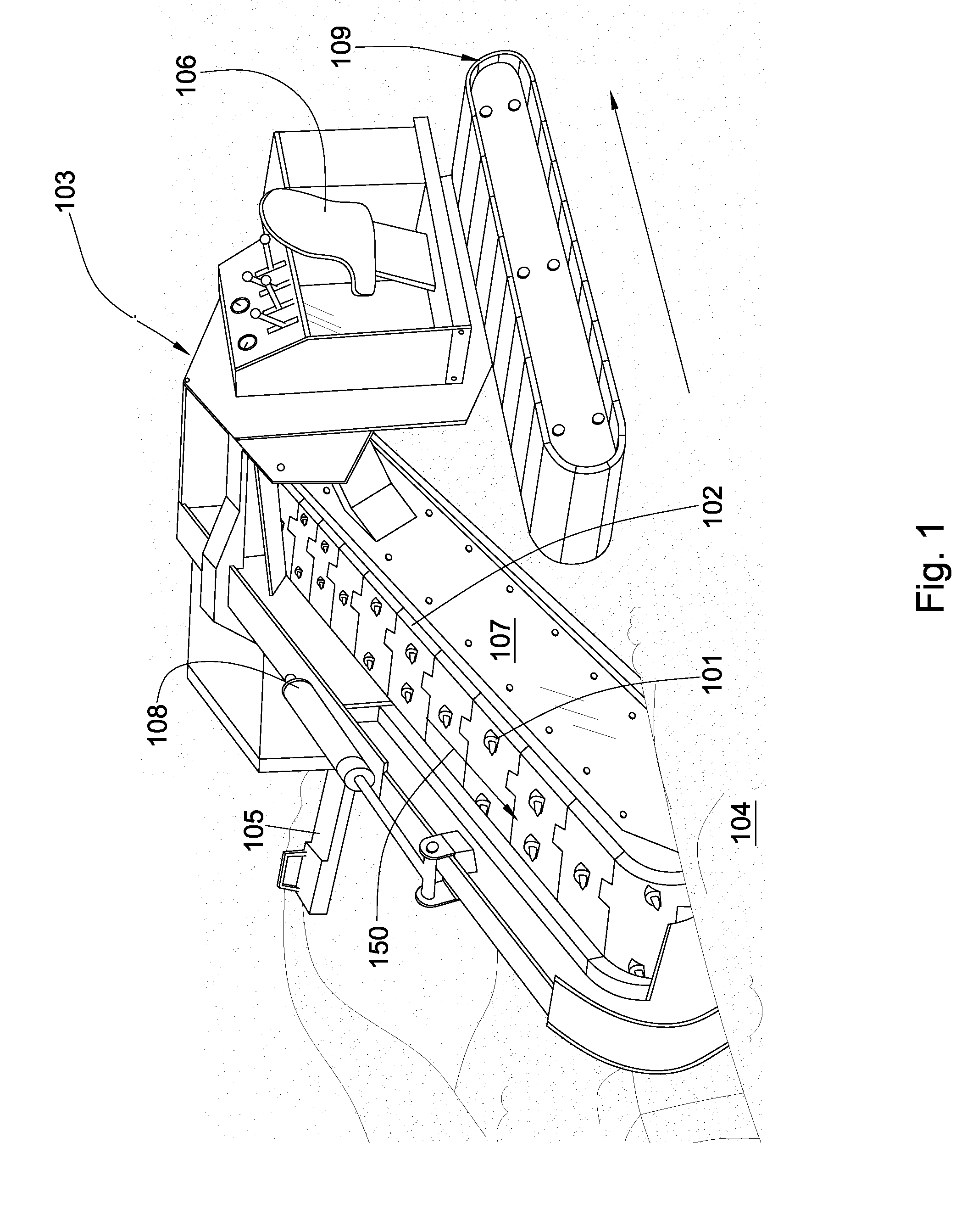
[0018]FIG. 1 illustrates a plurality of picks 101 on a rotating chain 102 attached to a motor vehicle 103, specifically, a trenching machine. In other embodiments, the picks may be adapted for attachment to a mining machine, pavement milling machine, or a combination thereof. The plurality of picks 101 may be exteriorly mounted in a “V” pattern on the chain 102 to facilitate degradation and removal of a formation 104. The rotating chain 102 rotates in a direction indicated by an arrow 150 and cuts the formation 104 forming a trench while bringing the formation cuttings out of the trench to a conveyor belt 105 which directs the cuttings to a side of the trench. The rotating chain 102 is supported by an arm 107. The arm 107 may be raised while the machine is being transported or it may be lowered for trenching as shown in FIG. 1. The position of the arm may be controlled by a hydraulic piston and cylinder 108. The trenching machine may move about the formation 104 by tracks 109, wheel...
PUM
| Property | Measurement | Unit |
|---|---|---|
| depth | aaaaa | aaaaa |
| thickness | aaaaa | aaaaa |
| thickness | aaaaa | aaaaa |
Abstract
Description
Claims
Application Information