Pressure-applying device

Inactive Publication Date: 2012-03-20
LABASH JOSIAH
View PDF36 Cites 19 Cited by
  • Summary
  • Abstract
  • Description
  • Claims
  • Application Information

AI Technical Summary

Problems solved by technology

As a result, many westerners are willing to try one or more of these methods, especially when other conventional methods have not been successful.

Method used


Image

  • Pressure-applying device
  • Pressure-applying device
  • Pressure-applying device

Examples


Embodiment Construction

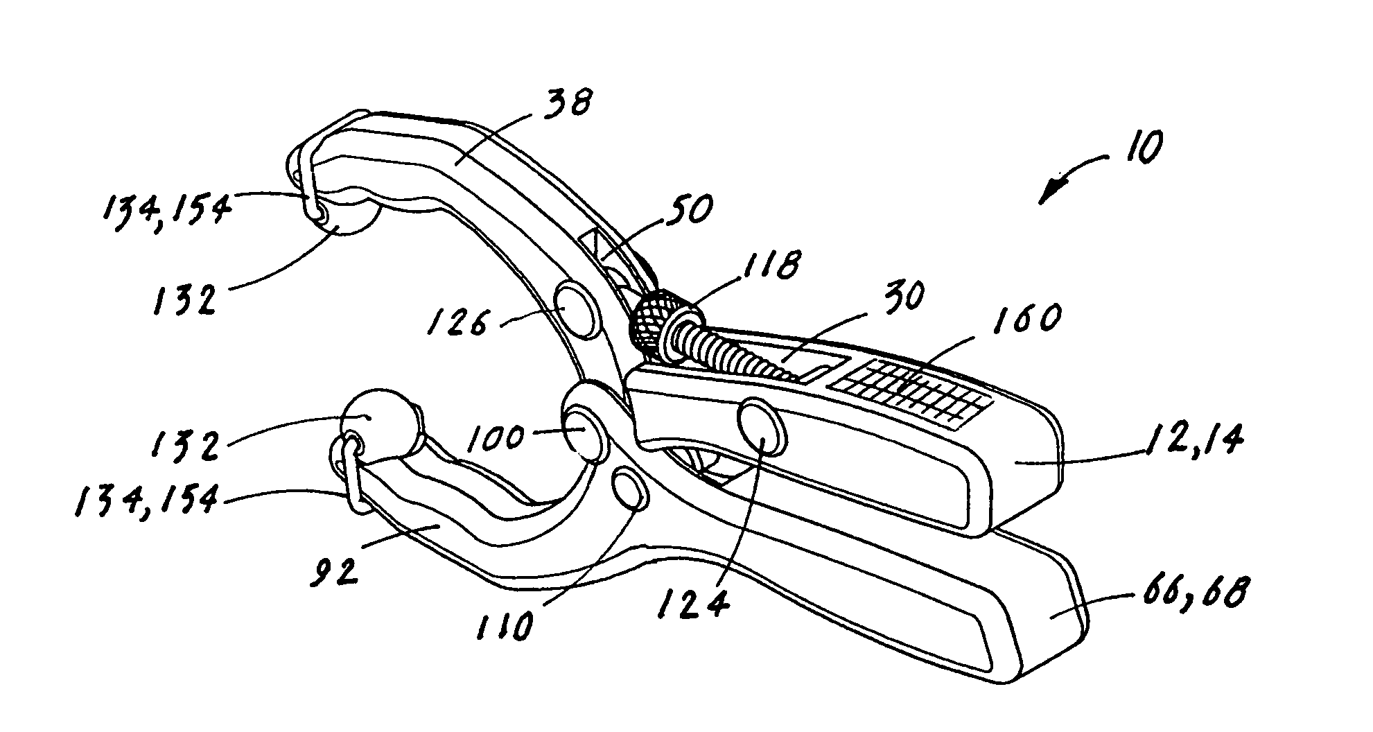
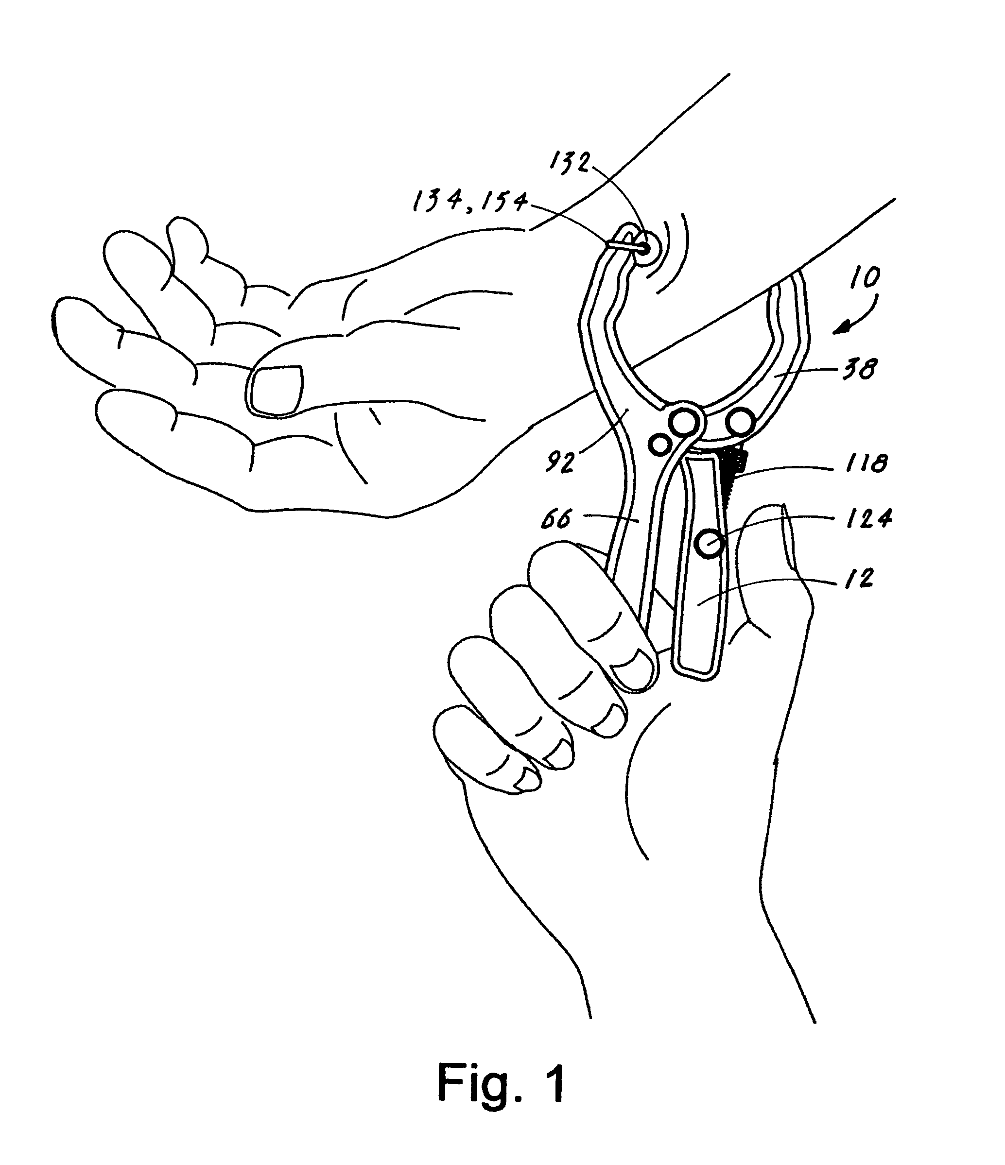
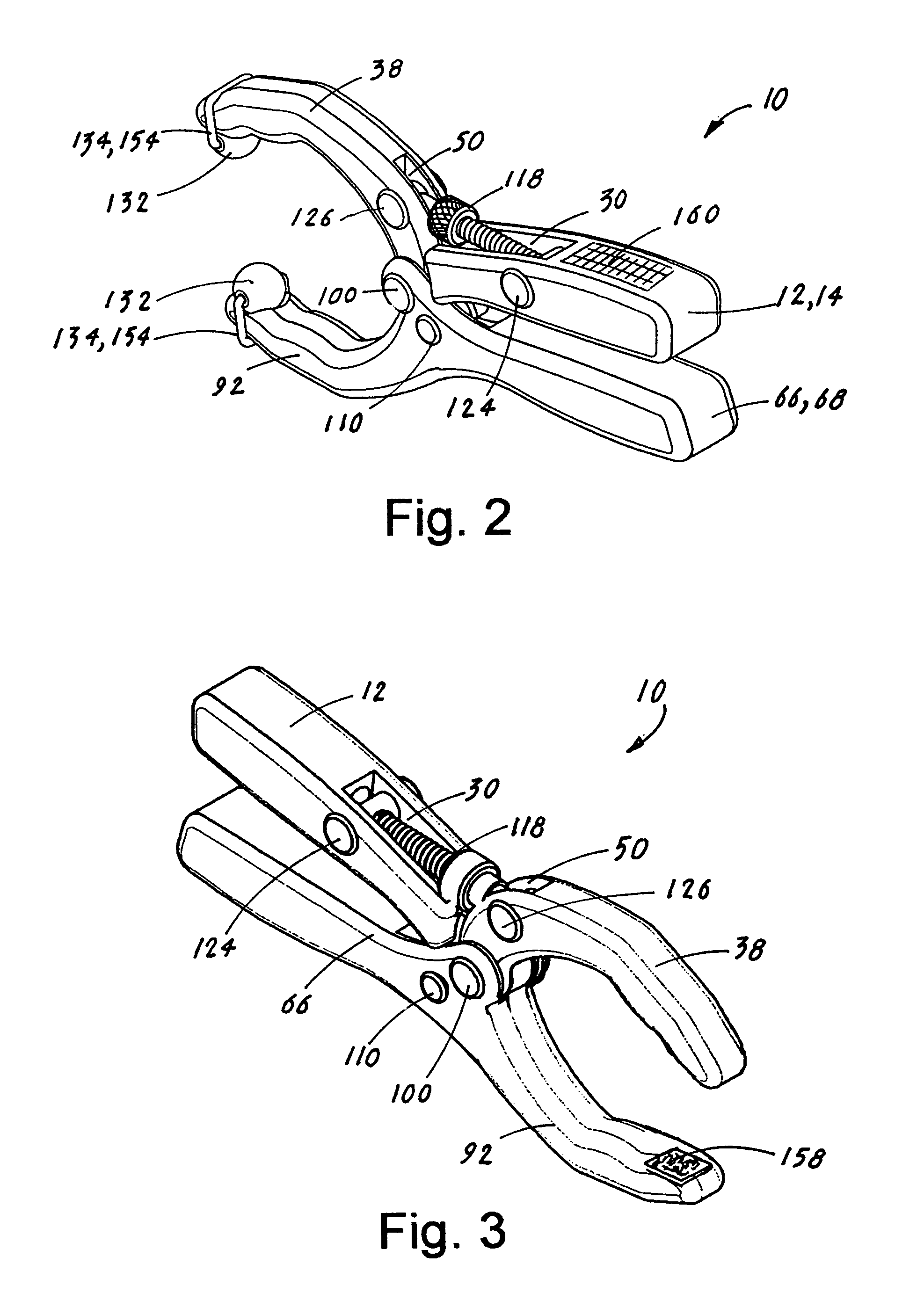
[0033]The best mode for carrying out the invention is presented in terms that disclose a preferred embodiment of a pressure-applying device 10 (“PAD 10”). As described herein and shown assembled in FIG. 1, and an exploded view in FIG. 7, the PAD 10 is designed to be attached to a selected location on a person's skin. The PAD 10 provides the therapeutic effects of pressure on the skin. The locations on a person's skin where the PAD 10 is attached are typically chosen according to traditional acupressure techniques.

[0034]As shown in FIGS. 1-7, the PAD 10 is comprised of a first handle 12 and a second handle 66. The two handles 12,66 are made of a material that is selected from the group consisting of plastic, metal or wood. As best shown in FIG. 7, the first handle 12 has a rear end 14, a front end 16, a front tab 18 with a tab bore 20, a first side surface 22, a second side surface 24, an inner surface 26, an outer surface 28 with a handle slot 30, and a bore 32. Longitudinally exten...


PUM

PropertyMeasurementUnit
pressureaaaaaaaaaa
forceaaaaaaaaaa
timeaaaaaaaaaa

Abstract

A pressure-applying device (PAD) (10) that is attached to a selected location on a person's skin for therapeutic purposes. The PAD (10) comprises a first handle (12) having an articulated arm (38) with a tip (40) and a second handle (66) having an integral arm (92) with a tip (94). The first handle (12) is swively attached to the second handle (66) at a spring-loaded pivot point that allows the device (10) to be pressure-attached to the skin. A magnetic or non-magnetic sphere (132) is attached to each respective tip (40,94). When the PAD (10) is attached to a person's skin the sphere is pressure-interfaced on the skin. A tension screw (46) interfaces with the two handles (12,66) and allows the PAD (10) to apply adjustable pressure. The locations on person's skin where the PAD (10) is attached are designated according to traditional acupressure techniques.

Description

TECHNICAL FIELD[0001]The invention generally pertains to therapeutic products, and more particularly to a pressure-applying device that is attached to a selected location on a person's skin for a therapeutic purpose such as acupressure.BACKGROUND ART[0002]Holistic and / or non-western health practices have become widely used alternatives to conventional health / medical methodology. Many of the holistic / non-western practices utilize natural organic medicines and / or ancient techniques such as acupuncture, acupressure and magnetic therapy. Although the actual medical benefit(s) of acupuncture, acupressure or magnetic therapy have not been proven by western scientists / doctors, many people claim significant improvement in a medical condition as a result of these methods. Whether the improvement is actual or psychological does not matter to the proponents as long as they experience the benefits. As a result, many westerners are willing to try one or more of these methods, especially when oth...

Claims


Application Information

Patent Timeline
Patent Type & Authority Patents(United States)
IPC IPC(8): A61B17/00
CPCA61H39/04A61N2/002Y10T29/539A61N2/06
Inventor LABASH, JOSIAH
Owner LABASH JOSIAH
Why Eureka
Try Eureka