Patellar components

a technology of patellar components and components, applied in the field of patellar components, can solve the problems of increasing the pain of patients, weakening and breaking of the pegs that extend from the patellar component and attach the component to the natural patella, and affecting the patient's comfort, so as to reduce or minimize the shear force, reduce the pain of the anterior knee, and reduce the effect of implantation error

Active Publication Date: 2012-03-27
SMITH & NEPHEW INC
View PDF118 Cites 3 Cited by
  • Summary
  • Abstract
  • Description
  • Claims
  • Application Information

AI Technical Summary

Benefits of technology

[0018]Embodiments of the present invention provide patellar components that are shaped to reduce or minimize shear force and accommodate slight implantation error. Further, embodiments may lessen anterior knee pain, particularly during deep-flexion activities and ease the transition during the range of knee movement in a controlled way.
[0027]A further embodiment provides a substantially axis-symmetric section that facilitates mal-rotation tolerance in use.
[0039]According to a further embodiment, this aspect may also have one or more reduced portions at the superior edge surface, the inferior edge surface, or both, to allow a smooth transition over the femoral component during flexion and extension.

Problems solved by technology

Some of this gap can be attributed to scarring within the knee joint and other physical conditions, but the remainder can be attributed primarily to failure of current implants to provide the proper prosthetic component geometries that take into consideration the natural kinematics of the knee.
Thus, despite the relative success of some products on the market, many patellar components tend to fail after about five to fifteen years.
Part of the reason they fail is due to excessive wear at certain regions of the component or loosening at the bone / component interface.
For example, with a dome patellar component, one reason for failure is the downward forces of the femoral component acting on the patellar component during flexion can cause the pegs that extend from the patellar component and attach the component to the natural patella to weaken and break.
In fact, a number of artificial patella failures are due to peg failures, and these types of forces can be painful for the patient.
Part of the reason that shear force causes a problem with artificial patellar components and not with a natural patella is because artificial patellar components tend to be shaped like an arc or a dome, whereas the natural patella is more linear shaped.
However, they can be particularly sensitive to high contact stress edge loading due to mal-rotation or positioning during surgical implantation.
This magnified constraint difference causes the anatomic patellar components to shift their alignment (equilibrium) with respect to the femoral component (particularly in rotational degrees of freedom) when moving from one area to the other, which can be perceived as an instability, pain, or a clunk to the patient.
The design challenge faced is to design surfaces of patellar components that minimize the shift in constraint, while still reducing the component / bone shear forces.
Another challenge experienced by patellar component manufacturers is to design a component that lessens the shear force issues described, but that also accommodates variations introduced by surgical inaccuracy and patient anatomical variation.
For example, it is difficult to position a patellar component so that it precisely matches the orientation of the patello-femoral groove geometry on the femoral component.
Accordingly, most designs on the market use an axis-symmetric configuration for the bearing surface of the patellar component (as shown in FIGS. 1-3), which results in a low conformity between the patellar component part and the femoral component.
However, such components cause the above-described shear force problems due to their shape.
Other designs have attempted to make patellar components flatter or more concave, so that they more closely approximate a natural patella, but as the components are made flatter, they are more to sensitive positioning error.
Due to a lack of precise instruments, data, and information, it can be difficult to surgically arrange for the rotational positioning of an anatomic patellar component so that it precisely matches the orientation of the patello-femoral groove geometry on the femoral component.
When non-axis-symmetric patellar components are not implanted at the proper position, it can cause ever greater wear concerns than the axis-symmetric designs discussed above.
While these components theoretically allow for a larger surface contact area between the patellar component and the femoral component, they are also extremely sensitive to alignment (particularly rotational alignment and the inclination of the patellar component to the natural patellar bone).
When surgical accuracy is not absolute, the error in alignment can cause edge loading and excessive fixation loading of the patellar component.
Another problem experienced by conforming, anatomically-shaped patellas (such as saddle-shaped patellas) is that they have different constraint patterns with the femoral component throughout the range of flexion.
As previously mentioned, it can cause pain and may also be perceived by the patient as instability as the transition may be non-linear and possibly inconsistent from one area to another.

Method used


Image

  • Patellar components
  • Patellar components
  • Patellar components

Examples


Embodiment Construction

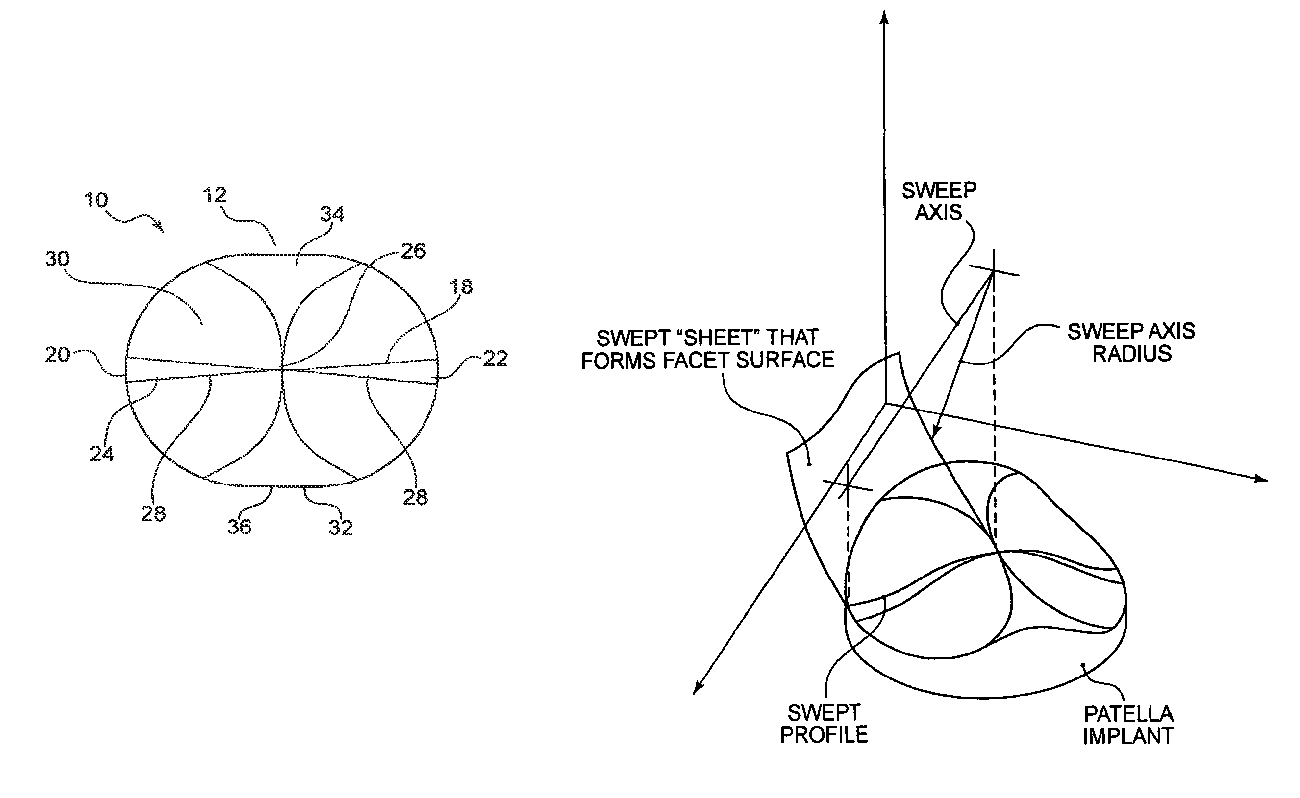
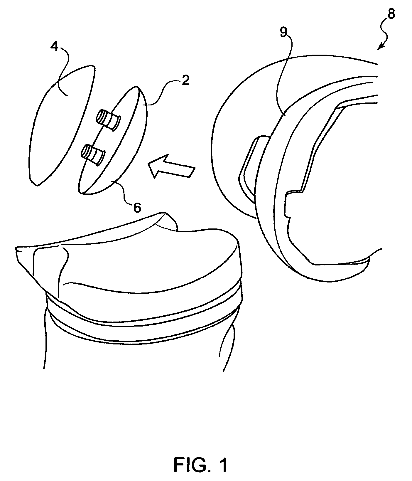
[0082]Embodiments of the present invention provide patellar prostheses that are designed to form a patella portion that replaces a part of a natural patella. The embodiments may decrease the shear force that is experienced by traditional dome-shaped patellar components, while also providing ease of implantation and accommodating a range of surgical error.

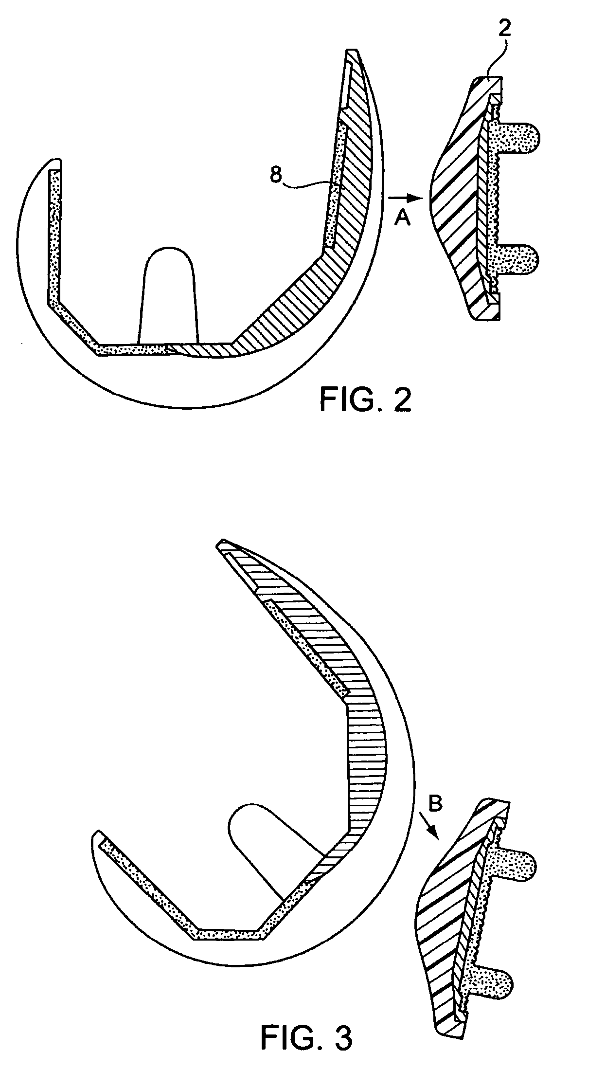
[0083]In order to reduce component / bone interface shear forces, which can be a source of pain and component failure, the ideal articular surface for a patellar component has a substantially flat profile. However, in order to increase contact area for better durability, the ideal articular surface substantially matches the coronal and sagittal profile of the trochlear groove of the femoral component. Finally, in order to allow for rotational laxity (surgical error), the ideal articular surface is axis-symmetric (like the button or circular patellar components discussed above). Embodiments of the patellar components described are an a...


PUM


Abstract

Embodiments of the present invention provide patellar component designs that are optimally shaped to help reduce shear force and accommodate slight implantation error. Further, they help lessen anterior knee pain, particularly during deep-flexion activities and help ease the transition during the range of knee movement in a controlled way.

Description

CROSS REFERENCE TO RELATED APPLICATIONS[0001]This application is the United States national phase of International Application No. PCT / US2007 / 002041 filed on Jan. 23, 2007 and published in English on Sep. 13, 2007 as International Publication No. WO 2007 / 102951 A2, which application claims the benefit of U.S. Provisional Application Ser. No. 60 / 761,296 filed on Jan. 23, 2006 entitled “Low Shear Force Patella;” U.S. Provisional Application Ser. No. 60 / 761,297 filed on Jan. 23, 2006 entitled “Controlled Constraint Anatomic Patella;” and U.S. Provisional Application Ser. No. 60 / 761,298 filed on Jan. 23, 2006 entitled “Convex Oval Patella,” the entire contents of each of which are hereby incorporated by reference.BACKGROUND OF THE INVENTION[0002]The present invention relates generally to patellar components that are designed to form a patella portion (or knee cap) that replaces a part of a natural patella or knee cap, and particularly to patellar components that are designed to cooperat...

Claims


Application Information

Patent Timeline
Patent Type & Authority Patents(United States)
IPC IPC(8): A61F2/38
CPCA61F2/3877
Inventor MCKINNON, BRIAN W.OTTO, JASON K.
Owner SMITH & NEPHEW INC
Why Eureka
Try Eureka