Safety lamp bulb connector assembly

a lamp bulb and connector technology, applied in the direction of fixed installation, coupling device connection, lighting and heating apparatus, etc., can solve the problem that children cannot directly remove the lampshade, and achieve the effect of high level of safety

Inactive Publication Date: 2012-04-03
HSIAO MING JEN
View PDF5 Cites 37 Cited by
  • Summary
  • Abstract
  • Description
  • Claims
  • Application Information

AI Technical Summary

Benefits of technology

[0006]The present invention has been accomplished under the circumstances in view. It is one object of the present invention to provide a safety lamp bulb connector as...

Problems solved by technology

Because the lampshade is locked to the electric connector assembly by the retaining blocks and the screw after installation, a child cannot directly ...

Method used


Image

  • Safety lamp bulb connector assembly
  • Safety lamp bulb connector assembly
  • Safety lamp bulb connector assembly

Examples


first embodiment

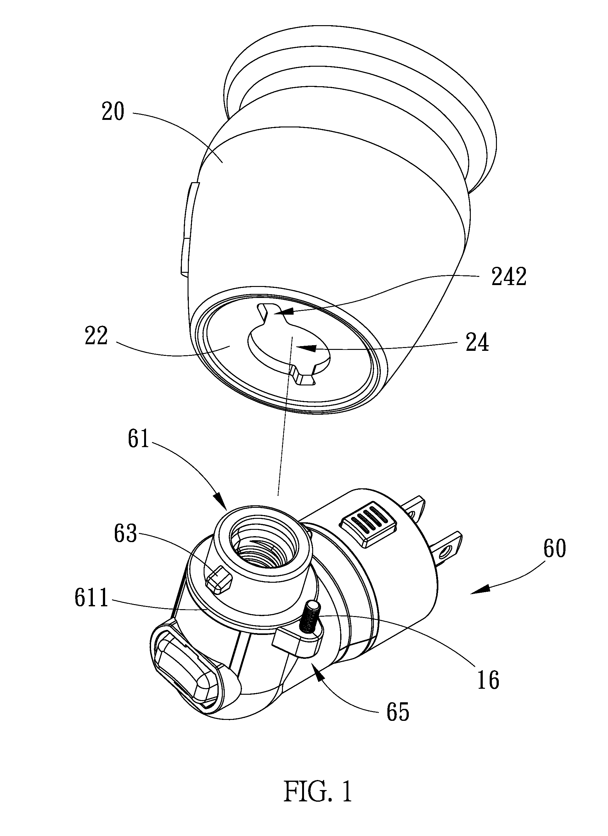
[0021]Referring to FIG. 1, a safety lamp bulb connector assembly in accordance with the present invention is shown comprising an electric connector assembly 60 and a lampshade 20. The electric connector assembly 60 includes a lamp socket 61, at least one, for example, two retaining blocks 63, and a screw holder 65. The lamp socket 61 is disposed at the top side of the electric connector assembly 60, having a bottom flange 611 extending around the periphery of the bottom side thereof. The two retaining blocks 63 are symmetrically protruded from the periphery of the lamp socket 61 at two opposite sides. The screw holder 65 is protruded from the periphery of a part of the electric connector assembly 60 adjacent to the bottom flange 611 of the lamp socket 61. The lampshade 20 comprises a bottom wall 22, a center opening 24 cut through the bottom wall 22, and at least one, for example, two notches 242 cut through the bottom wall 22 and radially extended from the center opening 24 in reve...

second embodiment

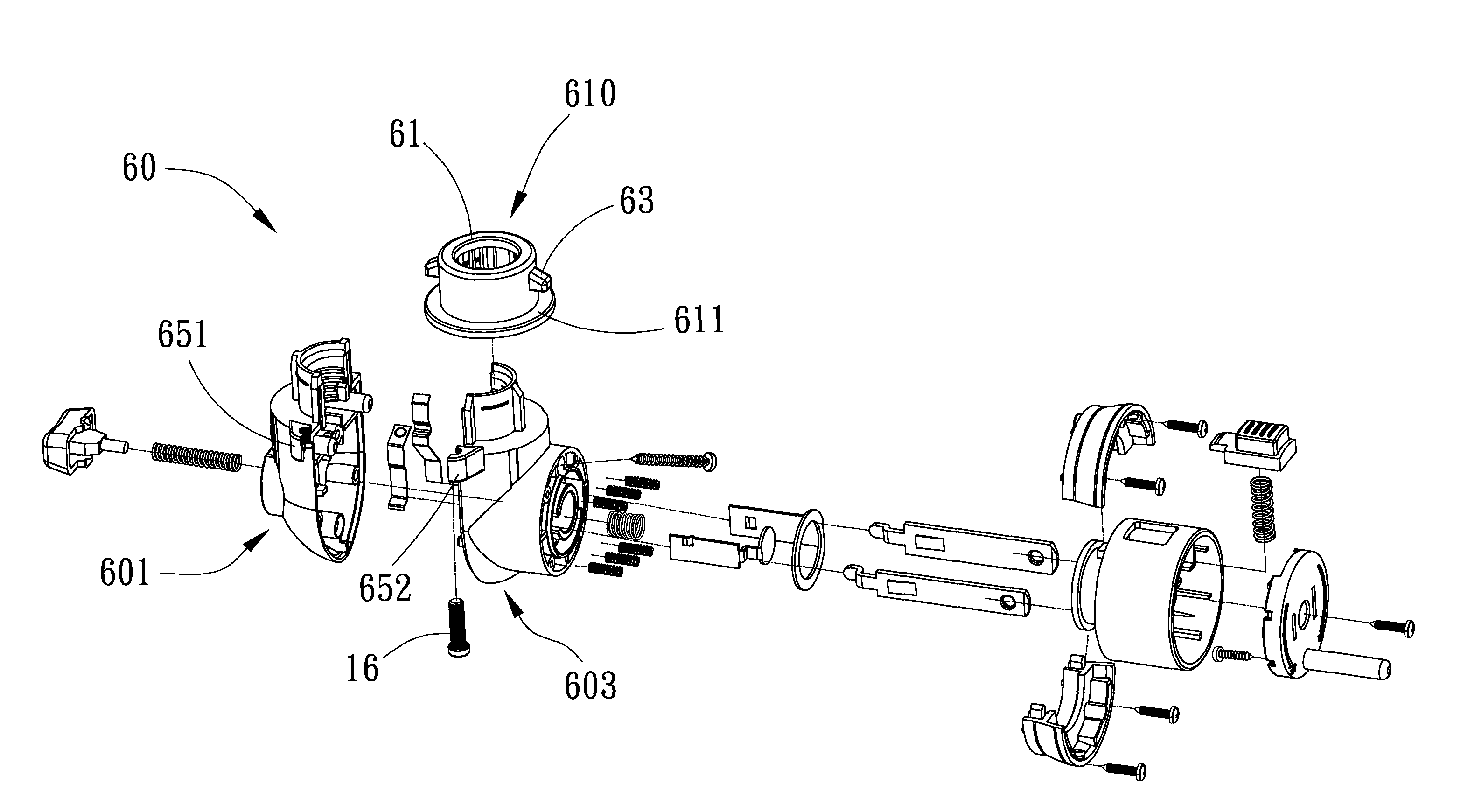
[0026]FIG. 4 illustrates a safety lamp bulb connector assembly in accordance with the present invention. According to this alternate form, the electric connector assembly 60 further comprises symmetric first shell 601 and second shell 603 and a socket 610. The symmetric first shell 601 and second shell 603 are abutted against each other and then fixedly fastened together. The aforesaid retaining blocks 63 are located on the periphery of the socket 610. The bottom flange 611 of the aforesaid lamp socket 61 is located on the bottom side of the socket 610. The bottom flange 611 of socket 610 is set in between the symmetric first shell 601 and second shell 603 and firmly secured thereto after fixation of the symmetric first shell 601 and second shell 603.

[0027]Further, the first shell 601 comprises a threaded arched block 651. The second shell 602 comprises a threaded arched block 653 matching the threaded arched block 651 of the first shell 601. When the first shell 601 and second shel...


PUM


Abstract

A safety lamp bulb connector assembly includes a lamp socket with a bottom flange, retaining blocks located on the periphery of the lamp socket and spaced above the bottom flange of the lamp socket, a screw holder disposed adjacent to the bottom flange of the lamp socket, a lampshade having a center opening cut through the bottom wall thereof for receiving the lamp socket and two notches radially outwardly extended from the center opening at two opposite sides for the passing of the retaining blocks for enabling the lampshade to be secured to the lamp socket after insertion of the retaining blocks through the notches and rotation of the lampshade through an angle relative to the lamp socket, and a screw mounted in the screw holder and inserted into one notch of the lampshell to prohibit rotation of the lampshade relative to the lamp socket.

Description

RELATED APPLICATIONS[0001]This application is a continuation-in-part of U.S. patent application Ser. No. 12 / 981,920, filed on Dec. 30, 2010.BACKGROUND OF THE INVENTION[0002]1. Field of the Invention[0003]The present invention relates to lighting fixtures and more particularly, to a safety lamp bulb connector assembly, which safety lamp bulb connector assembly, which prohibits a child from moving the lampshade from the lamp socket to touch the internal metal electric components accidentally, assuring a high level of safety.[0004]2. Description of the Related Art[0005]U.S. Pat. No. 6,921,180B2 discloses a lighting fixture entitled “Connector of a C-type bulb assembly”. which includes two half symmetric pieces, wherein the first piece having its two side projections provided with related rods and the second piece having its two side projections provided with related apertures. The two half pieces can be assembled together to become the connector while the bulb holder is connected there...

Claims


Application Information

Patent Timeline
IPC IPC(8): H01R33/00
CPCF21S8/035
Inventor HSIAO, MING JEN
Owner HSIAO MING JEN
Why Eureka
Try Eureka