Apparatus for mounting electrical and mechanical components on a support body

a technology for mounting electrical and mechanical components and accessories, which is applied in the direction of washstands, lighting support devices, coupling device connections, etc., can solve the problems of not being optimal with regard to functional function, complicated and relatively expensive, and not being optimal with regard to mounting rails. achieve the effect of simple manner

Active Publication Date: 2012-04-03
WEIDMULLER INTERFACE GMBH & CO KG
View PDF13 Cites 15 Cited by
  • Summary
  • Abstract
  • Description
  • Claims
  • Application Information

AI Technical Summary

Benefits of technology

[0017]It should be mentioned as especially advantageous that the assembly base sections can be stacked directly on one another to create the overlapping assembly base. However, in the simplest case the assembly base may also consist only of one of the assembly base sections. The preferred assembly base sections are especially simple and reliable to handle in this regard.
[0021]It has again been found to be especially advantageous if the receiving grooves form a type of inverted L-shape or T-shape configuration because the L-shape or T-shape allows implementation of mechanical locking on a base leg in an especially simple manner, whereas the transverse leg of the L-shaped or T-shaped receiving grooves makes it possible to perform separate contacting of a bus rail only following engagement of the electric components. An I-shape with a preliminary lock and a final catch / switch position in various heights of the contour would also be conceivable.

Problems solved by technology

From a mechanical standpoint, this type of fastening has proven successful, but the mounting rails are not optimal with regard to their electric function.
To do so, it is known that bus rails can be engaged in or adhesively secured to the mounting rails, but this is complicated and relatively expensive and is still not optimal with regard to functionality.

Method used


Image

  • Apparatus for mounting electrical and mechanical components on a support body
  • Apparatus for mounting electrical and mechanical components on a support body
  • Apparatus for mounting electrical and mechanical components on a support body

Examples


Embodiment Construction

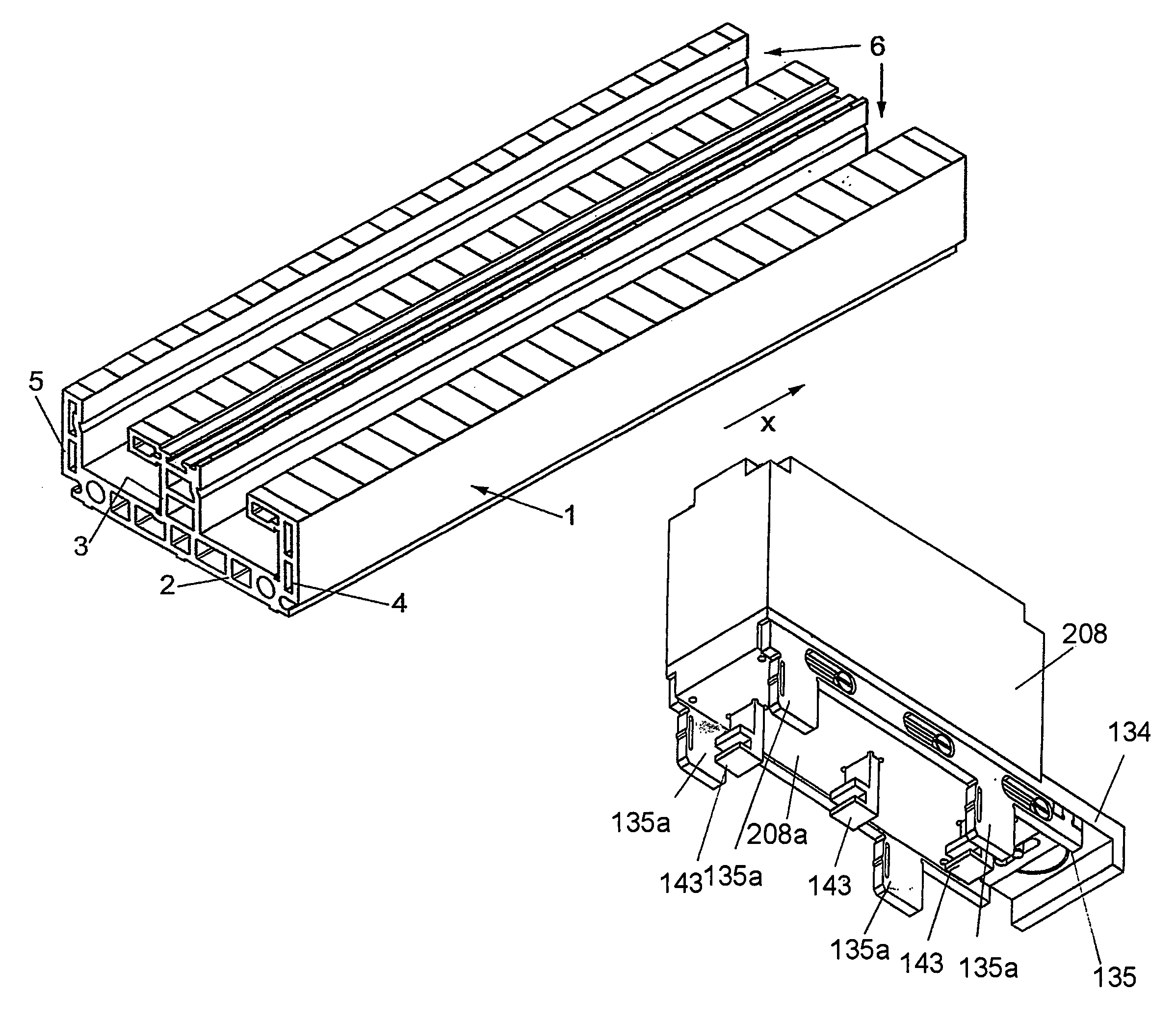
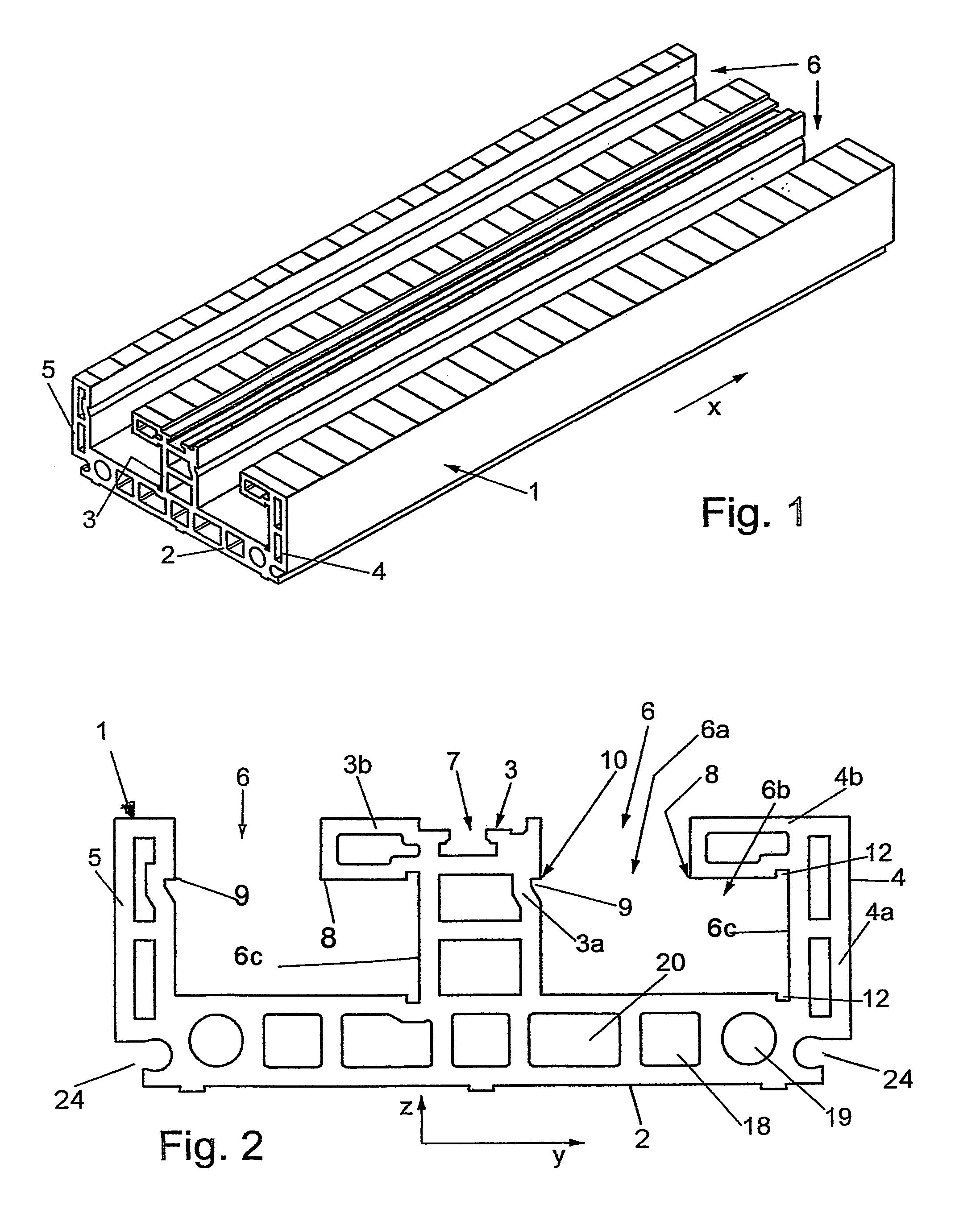
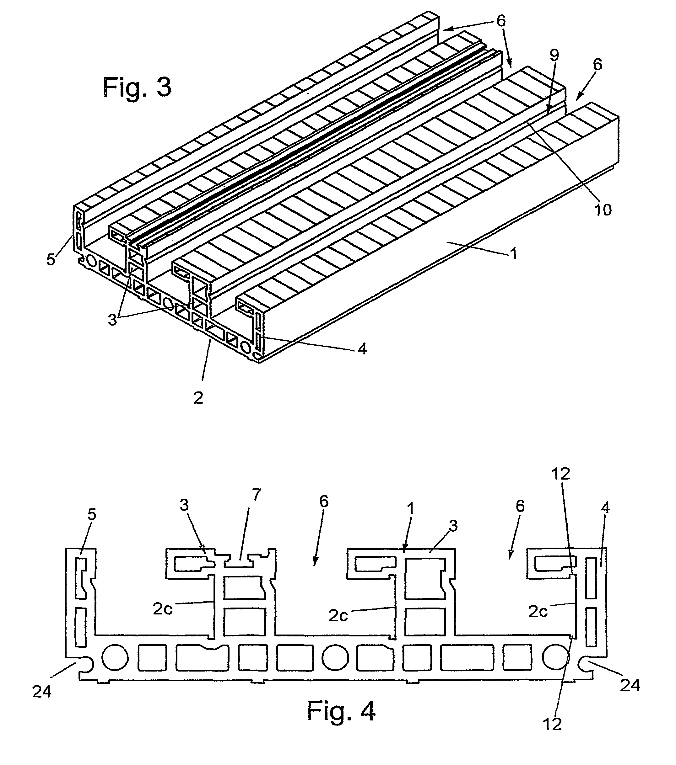
[0051]Referring first more particularly to FIGS. 21-23, the present invention relates to an arrangement for mounting an electrical component 34 upon a planar assembly of support bodies 1 having upper surfaces that contain a plurality of parallel longitudinal grooves 6. To this end, a connecting frame 35 is slidably connected with the lower surface of the component 34, which frame includes foot portions 35a that are adapted to extend downwardly into the grooves 6. When the component 34 is in the fully separated condition of FIG. 21, a plurality of contacts 43 extend downwardly from the bottom surface of the component 34. When the component 34 is displaced downwardly toward the insertion position of FIG. 22, the foot portions 35a of the frame 35 and the contacts 43 depending downwardly from the component 34 are displaced downwardly into the grooves 6, whereupon the component is seated in an initial position on the upper surface of the support body assembly. When the component 34 is sl...


PUM


Abstract

An electrical, electronic, fiber-optic, hydraulic, or pneumatic component is mounted upon a rectangular support body having an upper surface containing at least one linear groove, wherein a first connector is mounted in protectively concealed relation adjacent a given vertical side wall of the groove beneath an overhanging portion of the support body that extends partially into the groove, and a second connector extends downwardly from the component into the groove when the component is seated on the top surface of the support body. When the component is mechanically or manually horizontally displaced laterally of the groove from its initial inserted position toward a connected position adjacent the given vertical wall, the second connector is brought into connection with the first connector. In the preferred embodiment, the first and second connectors are electrical devices connected with electrical or electronic circuits contained within the component.

Description

BACKGROUND OF THE INVENTION[0001]1. Field of the Invention[0002]An electrical, electronic, fiber-optic, hydraulic or pneumatic component is mounted upon a rectangular support body having an upper surface containing a linear groove, wherein a first connector is mounted in protectively concealed relation on a given vertical side wall of the groove beneath an overhanging portion of the support body that extends partially into the groove, and a second connector extends downwardly from the component into the groove when the component is seated on the top surface of the support body. When the component is mechanically or manually horizontally displaced laterally of the groove from its initial inserted position toward a connected position adjacent the given vertical wall, the second connector is brought into connection with the first connector.[0003]2. Description of Related Art[0004]For assembly of stackable electric components and / or devices, e.g., modular terminals or electronic housing...

Claims


Application Information

Patent Timeline
Patent Type & Authority Patents(United States)
IPC IPC(8): H01R25/00
CPCH02B1/21H02G5/025
Inventor BURY, JOACHIMSCHULZE, RAINERSALOMON, THOMAS
Owner WEIDMULLER INTERFACE GMBH & CO KG
Why Eureka
Try Eureka