
Medium-voltage or high-voltage switching or control device, in particular a switchgear assembly

a control device and high-voltage technology, applied in the direction of coupling device connection, non-enclosed substation, substation, etc., can solve the problems of unfavorable maintenance, unfavorable wiring technology, and inapplicability to standard wiring configuration

Active Publication Date: 2012-04-03
ABB (SCHWEIZ) AG
View PDF19 Cites 3 Cited by
  • Summary
  • Abstract
  • Description
  • Claims
  • Application Information

AI Technical Summary

Problems solved by technology

Owing to the multiplicity of possible functions and the equipment that is used in this case, a standardized wiring configuration is not practical.
The various installation locations of the numerous equipment items in the control cabinet and in the control cabinet door result in the following exemplary disadvantages:Increased use of terminal blocks because of the multiplicity of interfaces.The use of prefabricated cable harnesses is not practical, because of the large number of installation locations and equipment items.Lack of electrical plug connections on the components.Large amount of interconnection effort to produce all the functions.Wiring technology that is not maintenance-friendly.

Method used


Image

  • Medium-voltage or high-voltage switching or control device, in particular a switchgear assembly
  • Medium-voltage or high-voltage switching or control device, in particular a switchgear assembly
  • Medium-voltage or high-voltage switching or control device, in particular a switchgear assembly

Examples


Embodiment Construction

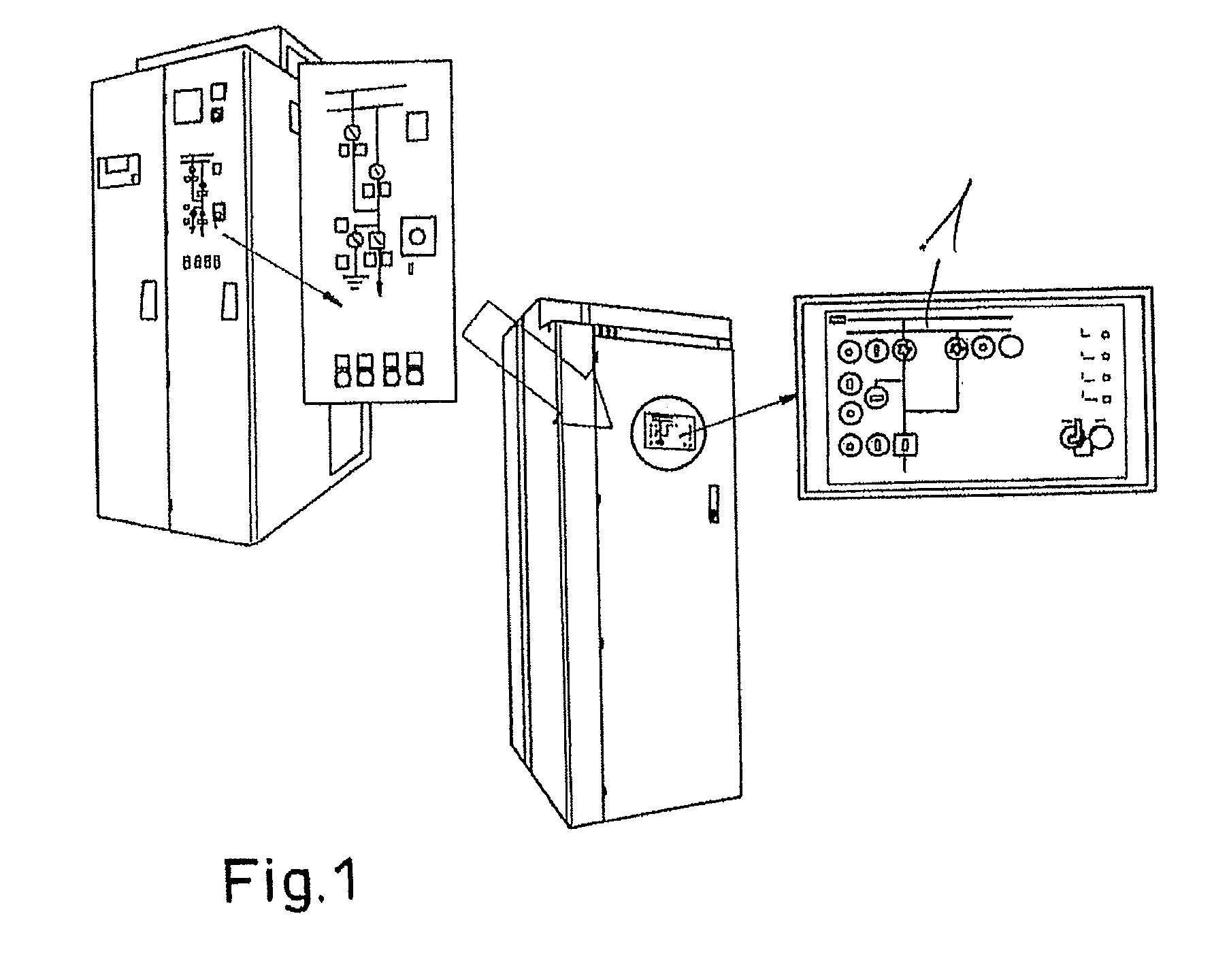
[0027]FIG. 1 shows an exemplary switchgear cabinet with an integrated box. Exemplary embodiments as disclosed herein can exploit advantages of microprocessor-controlled technology with known secondary technology.

[0028]Standards from an infinitely large number of different functions can be applied to a large number of switch panels, and recurrent functions can be combined to form a standard. Custom-specific functions can be at least partially standardized where possible.

[0029]Exemplary embodiments combine individual functions to form a standardized unit without departing from the known technology approach.

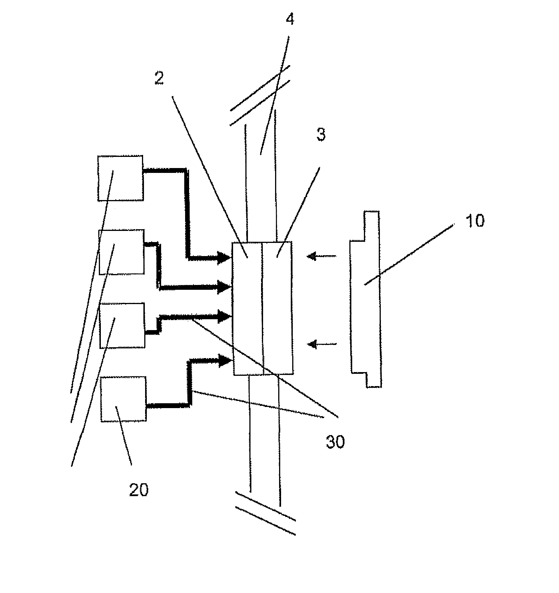
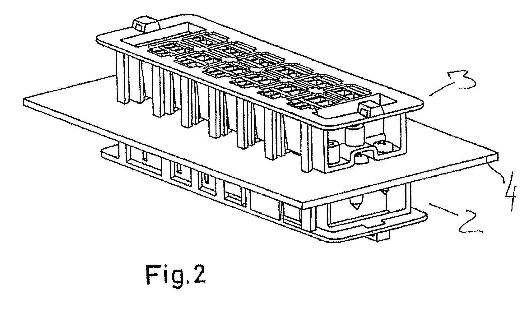
[0030]Electrical wiring between the electrical functional components of the switchgear assembly is replaced by wiring in a box or board, wherein the electrical components can be each connected directly to the box only by a bound cable run.

[0031]In another application of the function of the switchgear assembly to be implemented, the connections of the electrical components can be con...


PUM


Abstract

A switchgear assembly is disclosed wherein to combine individual functions to form a standardized unit, without deviating from known technology, electrical cabling between the electrical functional components of the switchgear assembly can be replaced by a wiring in a box. The electrical components can each be connected directly to the box by a bundle of bound cables. Another embodiment includes a coding plug for being plugged from the exterior.

Description

RELATED APPLICATIONS[0001]This application claims priority as a continuation application under 35 U.S.C. §120 to PCT / EP2008 / 002715, which was filed as an International Application on Apr. 4, 2008 designating the U.S., and which claims priority to German Application 10 2007 016 952.5 filed in Germany on Apr. 5, 2007 and German Application 10 2008 017 429.7 filed in Germany on Apr. 3, 2008. The entire contents of these applications are hereby incorporated by reference in their entireties.FIELD[0002]The disclosure relates to a low-voltage, medium-voltage or high-voltage switching or control device, such as a switchgear assembly, and to applications thereof.BACKGROUND INFORMATION[0003]Switchgear assemblies form components for electrical power transmission and distribution. Their versatile capabilities and complex functions can, on the one hand, contribute to general safety, and on the other hand can ensure the availability of electrical power.[0004]The basic design of known medium-volta...

Claims


Application Information

Patent Timeline
Patent Type & Authority Patents(United States)
IPC IPC(8): H01H27/00
CPCH02B15/00H02B1/306
Inventor SCHMIDT, KARL-MICHAELHENKE, RALFWEHRMANN, SVEN
Owner ABB (SCHWEIZ) AG
Learn More