Roll screen control member

a control member and roller technology, applied in the direction of curtain suspension devices, door/window protective devices, shutters/movable grilles, etc., can solve the problems of slipping or sliding, affecting the stability of the sprocket support, and raising the problem of only a single cutting surfa

Inactive Publication Date: 2012-04-17
UNI-SOLEIL ENT CO LTD
View PDF6 Cites 9 Cited by
  • Summary
  • Abstract
  • Description
  • Claims
  • Application Information

AI Technical Summary

Benefits of technology

[0008]Therefore it is a primary object of the present invention to provide a roll screen control member that makes a chain precisely drive a roll screen tube to rotate while the chain of the roll screen being pulled so that a screen of the roll screen can be extended or retracted smoothly.
[0009]In order to achieve above object, a roll screen control member of the present invention includes a sprocket wheel, a chain protection cover, a sprocket support, a cover spring, a splined bush and a central pin. The splined bush is mounted with a roll screen tube while the central pin includes a central pin head with a plurality of cutting surfaces. After the central pin being locked into the sprocket support, each cutting surface of the central pin matches and corresponds to each of a plurality of cutting surfaces of the sprocket support. Thereby while pulling the chain, due to precise matching and locking of the plurality of cutting surfaces of the central pin precisely with the plurality of cutting surfaces of the sprocket support, the chain drives the roll screen tube to rotate along with its movement through the sprocket wheel, the cover spring and the splined bush so as to control extension or retraction of the screen of the roll screen.

Problems solved by technology

However, in practice, such locking and fixing way by means of only a single cutting surface raises a problem.
When the chain moves so as to make the cover spring drive the splined bush rotating the roll screen tube, a spin or slide occurs once a transmission torque exerted is too large and the fixing between the central pin and the sprocket support is not so securely.

Method used


Image

  • Roll screen control member
  • Roll screen control member
  • Roll screen control member

Examples


Embodiment Construction

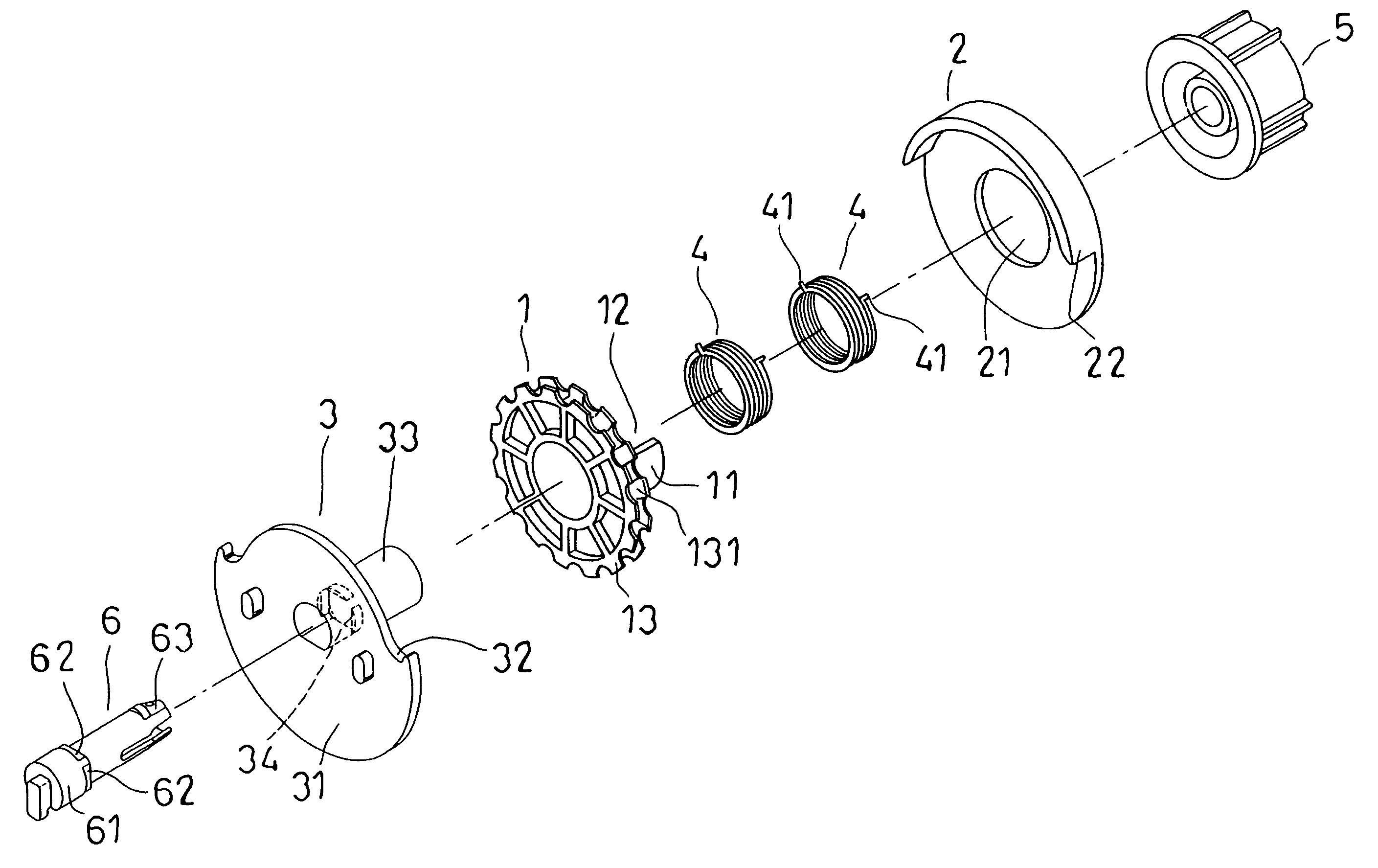
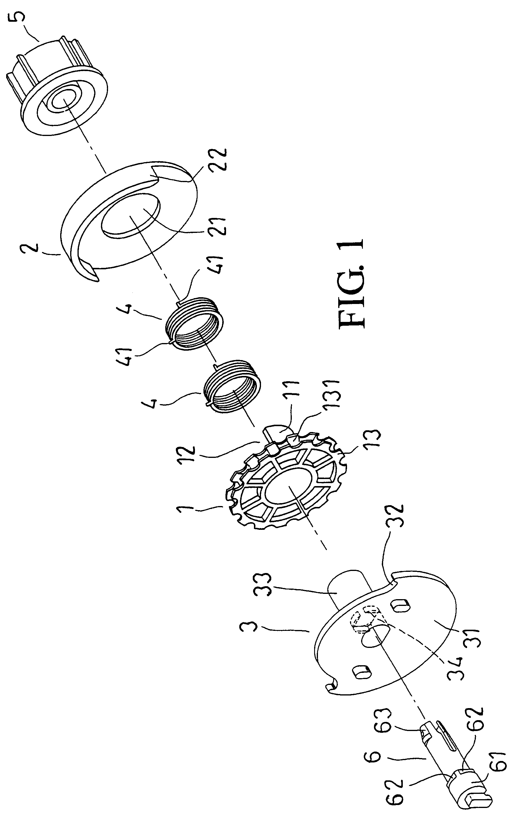
[0018]Refer from FIG. 1 to FIG. 3, a roll screen control member of the present invention consists of a sprocket wheel 1, a chain protection cover 2, a sprocket support 3, at least one cover spring 4, a splined bush 5 and a central pin 6.

[0019]The sprocket wheel 1 includes a shaft penetration part 11 on the center thereof, an open gap 12 formed over the shaft penetration part 11, a circular sprocket 13 on one end of the shaft penetration part 11 and a ball receiving slot 131 for accommodating balls of a ball chain (not shown in figure) arranged around the circular sprocket 13.

[0020]The chain protection cover 2 consists of an insertion hole 21 arranged at the center thereof and inserted by the shaft penetration part 11 of the sprocket wheel 1, a shield part 22 extended from top of an upper circle for covering the ball chain disposed on the circular sprocket 13 of the sprocket wheel 1.

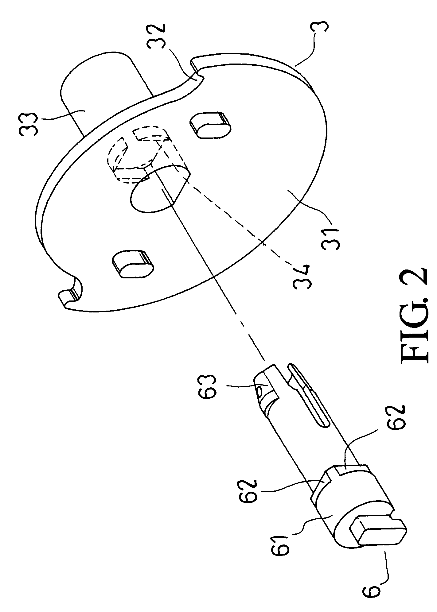
[0021]The sprocket support 3 is composed of a plate body 31 whose circumference is with a limiting par...


PUM


Abstract

A roll screen control member is revealed. The roll screen control member consists of a sprocket wheel, a chain protection cover, a sprocket support, a cover spring, a splined bush and a central pin. The splined bush is mounted with a roll screen tube while the central pin includes a central pin head with a plurality of cutting surfaces. After the central pin being locked into the sprocket support, each cutting surface of the central pin is corresponding to each cutting surface on the sprocket support. When a chain is pulled, due to the precise locking between the central pin and the sprocket support, splined bush is moved along with the cover spring so as to drive the roll screen tube to rotate along with the movement and further control extension or retraction of the roll screen.

Description

BACKGROUND OF THE INVENTION[0001]1. Fields of the Invention[0002]The present invention relates to a roll screen control member, especially to a roll screen control member with a novel design that drives a roll screen tube to rotate precisely and further controls an extended or retracted state of a screen of the roll screen.[0003]2. Descriptions of Related Art[0004]The roll screen control member available now is composed of a sprocket wheel, a chain protection cover, a sprocket support, a cover spring, a splined bush and a central pin. The splined bush is mounted with a roll screen tube while the central pin includes a central pin head with a single cutting surface corresponding to a cutting surface on an inner wall of the sprocket support. After the central pin being locked into the sprocket support, they are locked and fixed with each other by matching and corresponding of the cutting surface of the central pin head with the cutting surface on the inner wall of the sprocket support...

Claims


Application Information

Patent Timeline
Patent Type & Authority Patents(United States)
IPC IPC(8): E06B9/56
CPCE06B9/42E06B9/56E06B2009/905
Inventor KAO, YU-TING
Owner UNI-SOLEIL ENT CO LTD
Why Eureka
Try Eureka