
Safety switch control mechanism of exerciser

a safety switch and control mechanism technology, applied in the field of exercisers, can solve the problems of inability to ensure the accurate operation of the safety switch, the design of the safety switch is still not satisfactory in function, and the user is injured

Active Publication Date: 2008-09-11
HEALTHSTREAM TAIWAN INC
View PDF4 Cites 18 Cited by
  • Summary
  • Abstract
  • Description
  • Claims
  • Application Information

AI Technical Summary

Benefits of technology

"The present invention provides a safety switch control mechanism for an exerciser that accurately controls the power supply of the exerciser. The mechanism is special to prevent other objects from driving the power control switch, ensuring high security. The mechanism includes a linkage and a safety control key. The linkage is fixed to the inner wall of the instrument panel and has a pivot unit with a hook portion and a holding portion and a releasing portion. The safety control key has a grip and a plate-like actuation portion that inserts into the keyhole. The actuation portion has a through hole with opposite sides. When the actuation portion is inserted into the keyhole, it forces the pivot unit to rotate, either clockwise or counterclockwise, depending on the position of the actuation portion, to switch on or off the power supply of the exerciser. The technical effect of this invention is to provide a reliable and secure mechanism for controlling the power supply of an exerciser."

Problems solved by technology

Without the safety switch, the user's clothes may be rolled into the machine when the user falls from the machine accidentally during exercise, potentially injuring the user.
The aforesaid safety switch design is still not satisfactory in function.
Simply by means of inserting the plug pin into the safety switch or pulling the plug pin away from the safety switch cannot assure accurate operation of the safety switch.
Further, this design cannot prohibit a child from inserting a similar rod member into the safety switch and then potentially switching on the power supply of the exerciser.
Briefly, the security level of this design of safety switch is low.

Method used


Image

  • Safety switch control mechanism of exerciser
  • Safety switch control mechanism of exerciser
  • Safety switch control mechanism of exerciser

Examples


Embodiment Construction

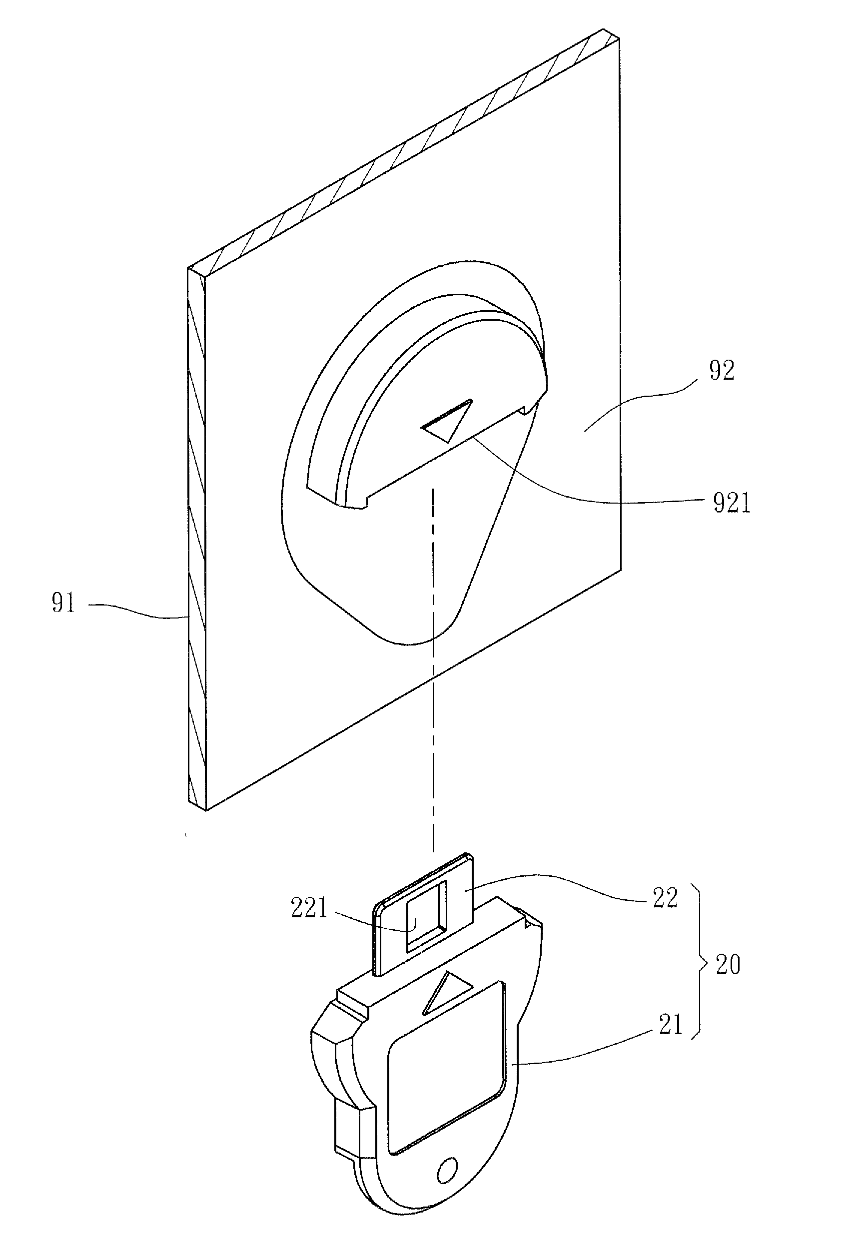
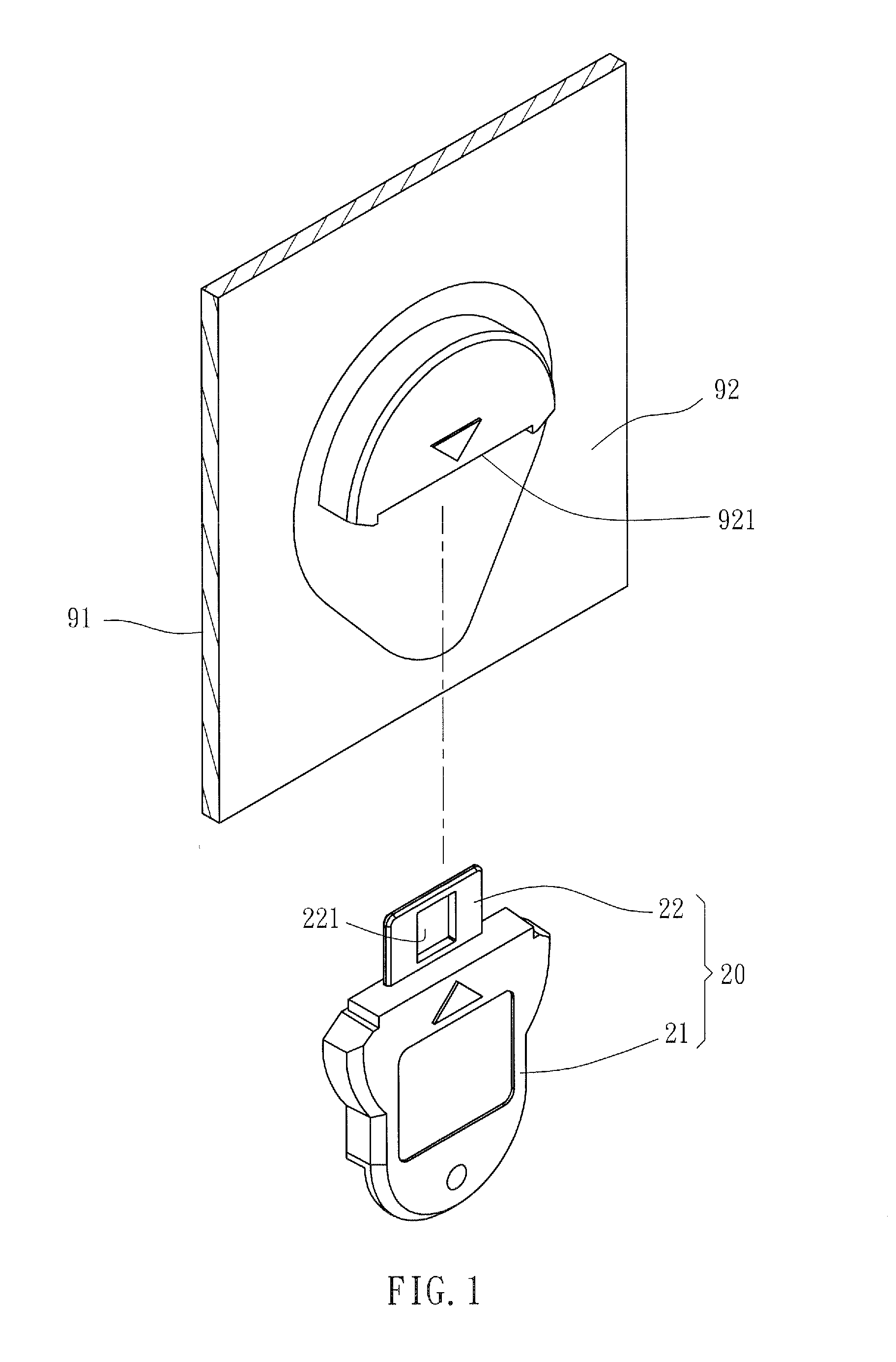
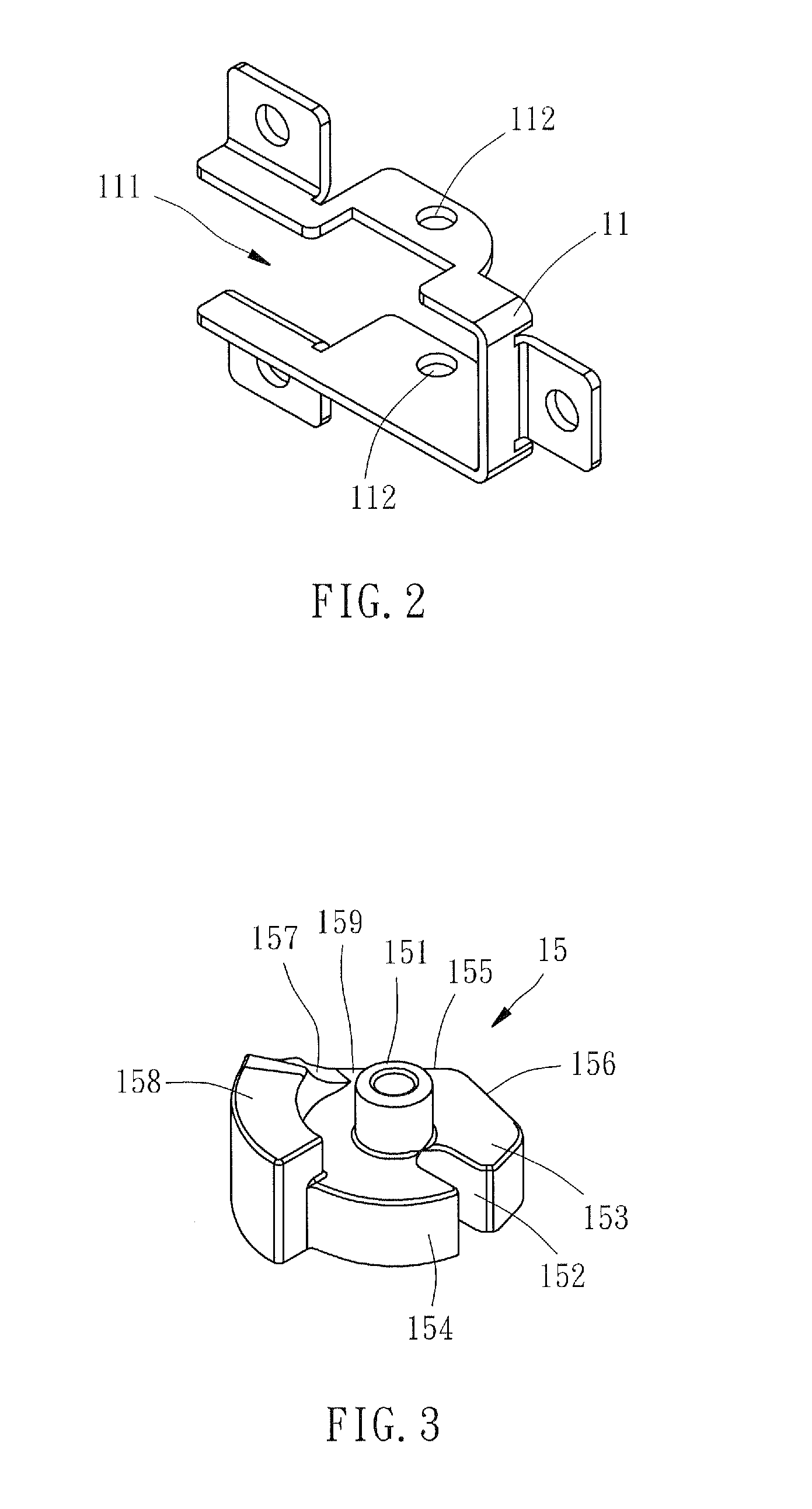
[0017]Referring to FIGS. 1-7, a safety switch control mechanism 100 in accordance with a preferred embodiment of the present invention is shown comprised of a linkage 10 and a safety control key 20.

[0018]The linkage 10 includes a bracket 11, a pivot unit 12, and a limiting springy piece 13. The bracket 11 is fixedly mounted to an inner sidewall 91 of an instrument panel (not shown) of an exerciser (not shown), having a central accommodation space 111 and two pivot holes 112 aligned at two opposite sides of the central accommodation space 111. The pivot unit 12 includes a pivot rod 14 and a wheel 15. The wheel 15 has a central axial hole 151. The pivot rod 14 is inserted through the central axial hole 151 of the wheel 15, having two opposite ends inserted through the two pivot holes 112 of the bracket 11 respectively to support the wheel 15 in the central accommodation space 111, allowing rotation of the wheel 15 on the pivot rod 14. The wheel 15 further has a radial retaining slot 1...


PUM


Abstract

A safety switch control mechanism includes a linkage and a safety control key. The linkage has a bracket mounted to an instrument panel of an exerciser and a wheel thereof rotatably mounted to the bracket. The instrument panel includes a keyhole located at an opposite side thereof to the bracket. The wheel has at least one hook portion formed at an outer periphery thereof, and a holding portion and a releasing portion formed at one side thereof. The safety control key has a through hole for engaging said at hook portion. When the safety control key is inserted into or pulled away from the keyhole, the sidewall of the through hole forces clockwise or counterclockwise rotation of the wheel to further shift the releasing portion for contact against a micro switch mounted to the instrument panel, and thus the micro switch is driven to switch on or off the power supply of the exerciser.

Description

BACKGROUND OF THE INVENTION[0001]1. Field of the Invention[0002]The present invention relates to exercisers and more specifically, to a safety switch control mechanism of an exerciser.[0003]2. Description of the Related Art[0004]An exerciser, for example, a treadmill has a safety switch to prevent a child's arbitrary, careless, or accidental triggering of the power control switch thereof from endangering the child, or to automatically switch off the power supply when the user falls from the machine accidentally during exercise. Without the safety switch, the user's clothes may be rolled into the machine when the user falls from the machine accidentally during exercise, potentially injuring the user. In such exerciser, the safety switch is installed in the instrument panel for switching on / off the power supply of the exerciser, and an extractable plug pin is inserted into the safety switch in linkage with the plug pin for turning on the power supply of the exerciser. A cord member is...

Claims


Application Information

Patent Timeline
Patent Type & Authority Applications(United States)
IPC IPC(8): H01H9/00
CPCH01H27/00A63B2071/0081
Inventor CHEN, YUAN-CHENTSENG, HUNG-CHIH
Owner HEALTHSTREAM TAIWAN INC
Learn More