Under voltage lock out circuit and method

a voltage lockout and circuit technology, applied in the direction of electric variable regulation, process and machine control, instruments, etc., can solve the problems of incorrect operation and failure of load circuits such as cpu, and achieve the effect of reducing the circuit area

Active Publication Date: 2009-02-03
ROHM CO LTD
View PDF13 Cites 17 Cited by
  • Summary
  • Abstract
  • Description
  • Claims
  • Application Information

AI Technical Summary

Benefits of technology

[0019]According to such embodiment, the threshold voltage is set with reference to both the comparison signal, which is the comparison result of the input voltage and the threshold voltage, and the start-up signal, and thus the start-up sequence is prevented from being executed in a state where start-up is not supposed to be started up.
[0026]According to such embodiment, the under voltage state is appropriately detected and ON / OFF of the regulator circuit can be controlled, so that the load connected to the regulator circuits can be driven properly.
[0027]In another embodiment, the power supply circuit may have the regulator circuits and the under voltage lock out circuit may be integrated on a single semiconductor substrate. “Integrated on a single semiconductor substrate” includes a case in which all the components of the circuit are formed on the semiconductor substrate and cases in which the main components of the circuit are integrated on a single semiconductor substrate, and thereby some of the resistors, capacitors and the like for adjustment of the circuit constant may be arranged exterior to the semiconductor substrate. By integrating the power supply circuit as one LSI, the circuit area may be reduced and also the user of the power supply circuit does not need to be aware of the sequence regarding the under voltage lock out on the inside.
[0029]According to such embodiment, the under voltage lock out may appropriately perform even if the voltage of the battery fluctuates in response to charging and discharging.

Problems solved by technology

The UVLO circuit triggers a problem in such case.
However, even if the start-up sequence is executed, the load circuits such as CPU may not be started up and may not operate correctly since the battery voltage Vbat is lower than the first voltage value Vth1.

Method used


Image

  • Under voltage lock out circuit and method
  • Under voltage lock out circuit and method
  • Under voltage lock out circuit and method

Examples


Embodiment Construction

[0040]The invention will now be described based on preferred embodiments which do not intend to limit the scope of the present invention but exemplify the invention. All of the features and the combinations thereof described in the embodiment are not necessarily essential to the invention.

[0041]The under voltage lock out circuit according to the embodiment of the present invention will now be described with reference to drawings. The same reference characters are denoted for the same or equivalent components, members, processes shown throughout the drawings, and descriptions will not be repeated.

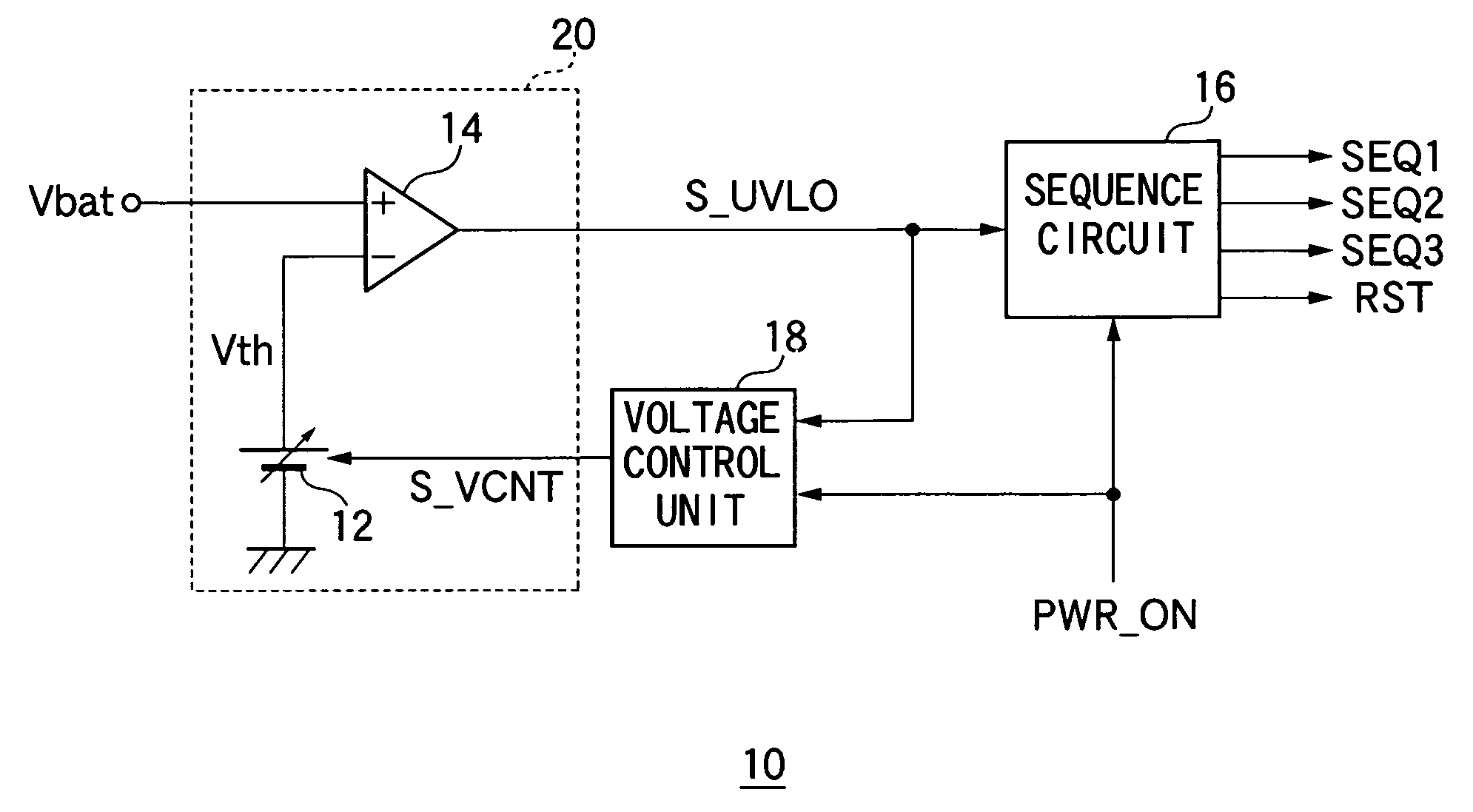
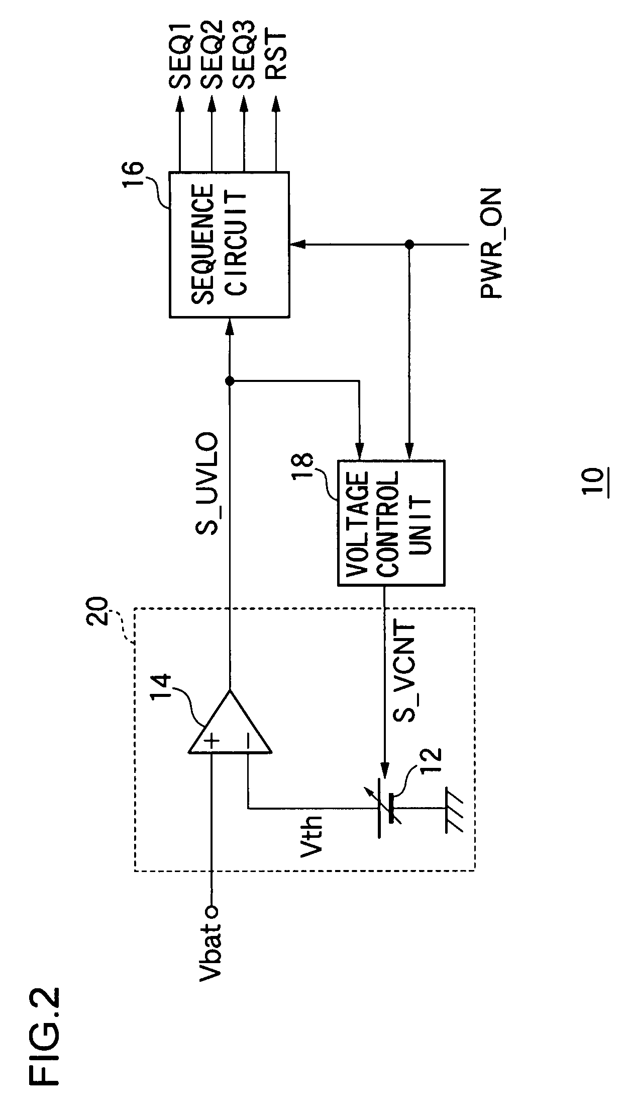
[0042]FIG. 2 is a circuit diagram showing a configuration of an UVLO circuit 10 according to the embodiment. FIG. 3 is a block diagram of a power supply circuit 100, in which the UVLO circuit 10 of FIG. 2 is suitably used, and the entire electronic equipment 1000. First, the configuration of the entire electronic equipment 1000 will be described with reference to FIG. 3. The electronic equip...


PUM


Abstract

A voltage comparison unit compares a battery voltage with a predetermined threshold voltage, and outputs a comparison signal. A sequence circuit receives the comparison signal and a start-up signal instructing start-up of equipment mounted with a UVLO circuit, and executes a predetermined sequence when start-up is instructed by the start-up signal in a state the battery voltage is higher than the threshold voltage. A voltage control unit switches the threshold voltage based on the comparison signal and the start-up signal.

Description

BACKGROUND OF THE INVENTION[0001]1. Field of the Invention[0002]The present invention relates to an under voltage lock out technique of monitoring the input voltage and preventing malfunction of circuits and devices in an under voltage condition.[0003]2. Description of the Related Art[0004]A great number of electronic circuits such as CPU (Central Processing Unit) and other DSP (Digital Signal Processor) which perform digital signal processing, liquid crystal panel and other analog circuits are mounted on recent various electronic equipments such as a mobile phone, a PDA (Personal Digital Assistant), a laptop computer and the like. The electronic circuits operate with power supplied from a battery or a power supply circuit for stabilizing the battery voltage.[0005]A stable operation guaranteed voltage is defined for each electronic circuit, and the relevant electronic circuit does not operate properly if the supplied voltage is lower than the stable operation guaranteed voltage. The...

Claims


Application Information

Patent Timeline
Patent Type & Authority Patents(United States)
IPC IPC(8): H02H3/24G05F5/00
CPCH02M1/36Y10S323/901
Inventor SASAKI, YOSHIKAZUHASHIMOTO, TETSUROYAMAMOTO, ISAO
Owner ROHM CO LTD
Why Eureka
Try Eureka