
Aircraft toilet facility

a technology for toilets and aircraft, applied in the direction of toilet fittings, aircraft components, air-treatment apparatus arrangements, etc., can solve the problems of aircraft operator potentially less profitable, aircraft less profitable, and large cabin space occupied by toilets

Inactive Publication Date: 2012-04-17
AIRBUS OPERATIONS LTD
View PDF12 Cites 3 Cited by
  • Summary
  • Abstract
  • Description
  • Claims
  • Application Information

AI Technical Summary

Benefits of technology

[0011]The first toilet unit may be at least partially in vertical alignment with the second toilet unit. The vertical direction is defined as that perpendicular to the floor of the passenger deck, the passenger deck defining the horizontal direction. That the first toilet unit is at least partially in vertical alignment with the second toilet unit means that at least some part of the first toilet is directly beneath, in the vertical direction, at least some part of the second toilet unit. Certain embodiments of the invention take advantage of the space in the aircraft body both above and below an aircraft passenger deck. The invention may be of particular benefit to the large, single passenger deck wide-bodied aircraft as mentioned above. For example, the aircraft may be between 50 m and 90 m in length and have a cabin width of between 4 m and 6 m. In large aircraft the sum of the under-floor space, the above-ceiling space and the cabin height may be sufficient to accommodate two toilet units, one above the other.

Problems solved by technology

However, the greater the number of toilets an aircraft carries, the greater the volume of cabin space taken up by the toilets.
This reduces the number of passengers that may be seated in the aircraft cabin, thereby making the aircraft potentially less profitable for the aircraft operator.
Aircraft for which this may particularly pose a problem include large, single passenger deck aircraft.

Method used


Image

  • Aircraft toilet facility
  • Aircraft toilet facility
  • Aircraft toilet facility

Examples


first embodiment

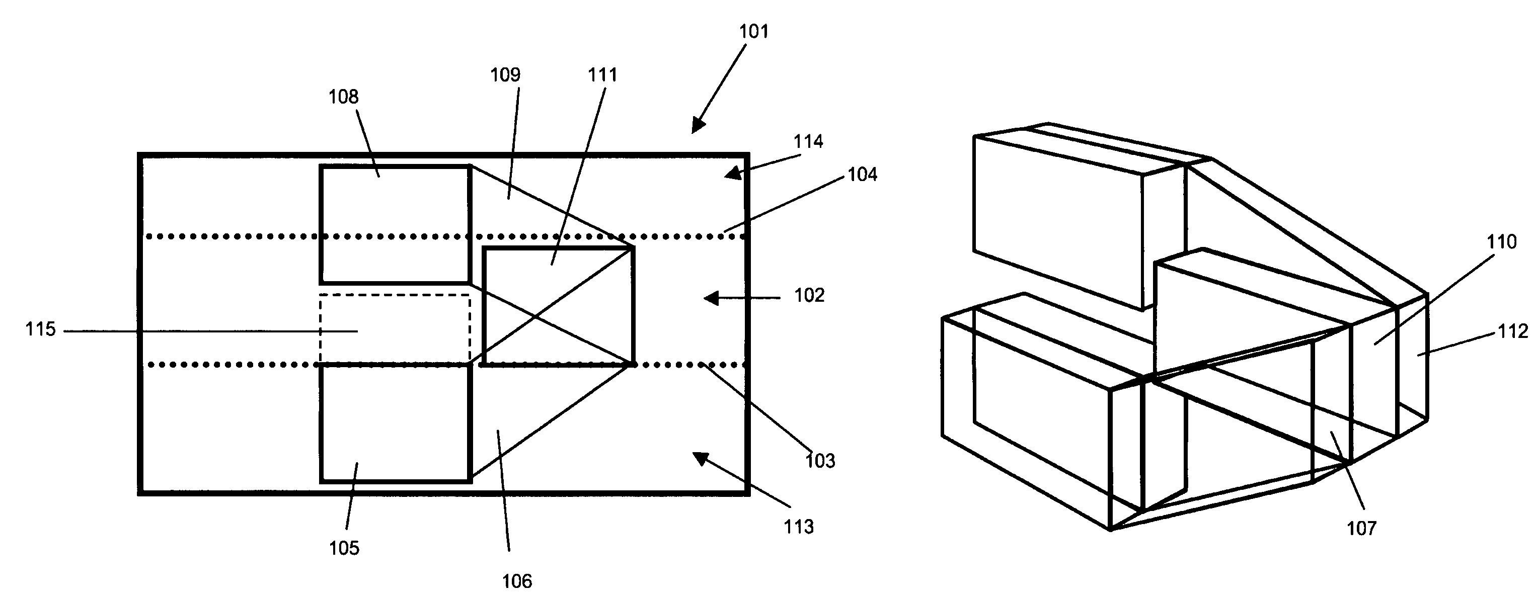
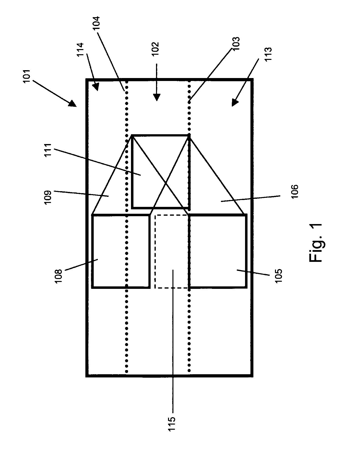
[0028]This first embodiment also shows a third toilet unit 111, fully located between the floor 103 and ceiling 104. The third toilet unit 111 is aligned in the same vertical plane as the first toilet unit 105 and second toilet unit 108. The third door 112 provides access to the third toilet unit 111 and the all three doors 107, 110, and 112, are located next to each other. Therefore, a passenger, when wanting to use the toilet facility, is presented with three doors next to each other.

[0029]As can be seen in FIG. 1, the arrangement of the first toilet unit and second toilet unit may be such that storage space 115 is provided between the units. There may be a gap of 0 mm to the height sufficient to include a further toilet unit between the top of the first toilet unit 105 and the bottom of the second toilet 108. Preferably, the storage space is accessible while the aircraft is flying. It may be accessible to the aircraft crew and / or the aircraft passengers. For example, the storage ...

second embodiment

[0032]FIG. 6 shows a plan view of the invention, as shown in FIGS. 4 and 5, where the first stair set 401 provides access (as indicated by arrows) to the side of the first toilet unit, and the second stair set 402 provides access to the side of the second toilet unit.

[0033]FIG. 7 shows plan view of an alternative to the second embodiment of the invention, where the first stair set 401 and the second stair set 402 include bends 401′ and 402′. The stair sets now provide access to the front of the toilet units (as indicated by an arrow). Advantageously, the first and second toilet unit may be front entry toilet units. This alternative to the second embodiment is equally applicable to the first embodiment as described above, where the ramps include a bend.

[0034]FIGS. 8, 9, and 10, show a third embodiment of the invention. The embodiment features an aircraft body 801, the aircraft body including a passenger deck 802, the passenger deck defined by a floor 803 and a ceiling 804, a first to...

fourth embodiment

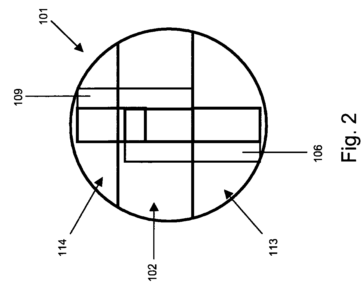
[0037]FIG. 11 shows the invention, comprising a first toilet unit 1101, a second toilet unit 1102, a third toilet unit 1103, a fourth toilet unit 1104 and a fifth toilet unit 1105. The arrangement is similar to that shown in FIGS. 4 and 5 as described above, with the addition of a the third toilet unit 1103 located beneath the floor of the passenger deck and the fifth toilet unit 1105 located in vertical alignment with the third toilet unit 1103 and partially within the above-ceiling space. In an alternative embodiment, access to the toilet units provided at least partially located in the space above or below the passenger deck may be provided by a ramp, as described in relation to FIGS. 1 to 3.

[0038]It will of course be appreciated that features described in relation to one embodiment of the present invention may be incorporated into other embodiments of the present invention.

[0039]Whilst the present invention has been described and illustrated with reference to particular embodime...


PUM


Abstract

The invention relates to an aircraft toilet facility, particularly an aircraft toilet facility on a single passenger-deck aircraft. The invention provides a first toilet unit situated at least partially in the space below the floor of a passenger deck of the aircraft, and a second toilet unit situated at least partially in the space above the ceiling of the passenger deck. The first toilet unit is proximate the second toilet unit, and both the first toilet unit and second toilet unit are accessible from the passenger deck.

Description

RELATED APPLICATIONS[0001]The present application is based on International Application Number PCT / GB2008 / 050284 filed Apr. 23, 2008, and claims priority from British Application Number 0708891.7 filed May 9, 2007, the disclosures of which are hereby incorporated by reference herein in their entirety.BACKGROUND OF THE INVENTION[0002]This invention relates to an aircraft toilet facility, more particularly, but not exclusively, an aircraft toilet facility on an aircraft with a single passenger deck.[0003]Aircraft, particularly commercial passenger aircraft, need to strike a balance between the number of passengers that they can carry, and the comfort in which those passengers are carried. For example, it is desirable to have a certain number of toilets on the aircraft depending on the number of passengers it is designed to carry. However, the greater the number of toilets an aircraft carries, the greater the volume of cabin space taken up by the toilets. This reduces the number of pas...

Claims


Application Information

Patent Timeline
Patent Type & Authority Patents(United States)
IPC IPC(8): B64D11/00
CPCB64D11/02B64D2011/0046Y02T50/46Y02T50/40
Inventor LYNAS, CHRISTOPHER
Owner AIRBUS OPERATIONS LTD
Learn More