Artificial heart pump

a heart pump and artificial heart technology, applied in the field of artificial heart pumps, can solve the problems of difficult adjustment of face-to-face distance, poor assembly performance, and worsening of the characteristic of red blood cell destruction, and achieve the effects of enhancing the assembly quality, and reducing the risk of heart failur

Inactive Publication Date: 2012-04-17
MITSUBISHI HEAVY IND LTD
View PDF49 Cites 31 Cited by
  • Summary
  • Abstract
  • Description
  • Claims
  • Application Information

AI Technical Summary

Problems solved by technology

In addition, not only an assembly performance is inferior, but also it is difficult to adjust the face-to face distance between the bearing, which is formed by the axial fixed body 102 and the rotor 122, and the face-to face distance between the bearing, which is formed by the axial fixed body 103 and the rotor 122, when the repulsive magnetic bearings are provided as shown in FIG. 26.
However, when the rotation speed is increased and becomes high, the characteristic of destruction of red blood cells will be worsened.
Therefore, the size of the artificial heart pump is limited, whereby the upper limit of the pressure thereof will be limited.
Furthermore, when the hydrodynamic bearings are configured as shown in FIG. 25, narrow gaps will be necessary for generating the hydrodynamic pressures, and as a result, due to the narrow gaps, there is a possibility that a blood clot may be formed easily or that red blood cells may possibly be destructed.
However, a contact is caused between the rotor and the fixed member at the back of the rotor due to a magnetic force of repulsion during an operation under a condition that the hydro thrust load is small and during start-ups and shutdowns.
In addition, depending on the operation condition, there is a possibility that a contact may be caused between the rotor and the fixed members that are in front of and at the back of the rotor.
With such a configuration as shown in FIG. 25, only the convex portion of a hydrodynamic bearing gap is in contact, but the contact area thereof is relatively large, so that there is a problem with a durability thereof.
Moreover, by such a configuration as described hereinabove, there are possibilities that abrasion powders may be generated due to the contact of the rotor with the fixed bodies and that a blood clot and a destruction of red blood cells may occur.

Method used


Image

  • Artificial heart pump
  • Artificial heart pump
  • Artificial heart pump

Examples


first embodiment

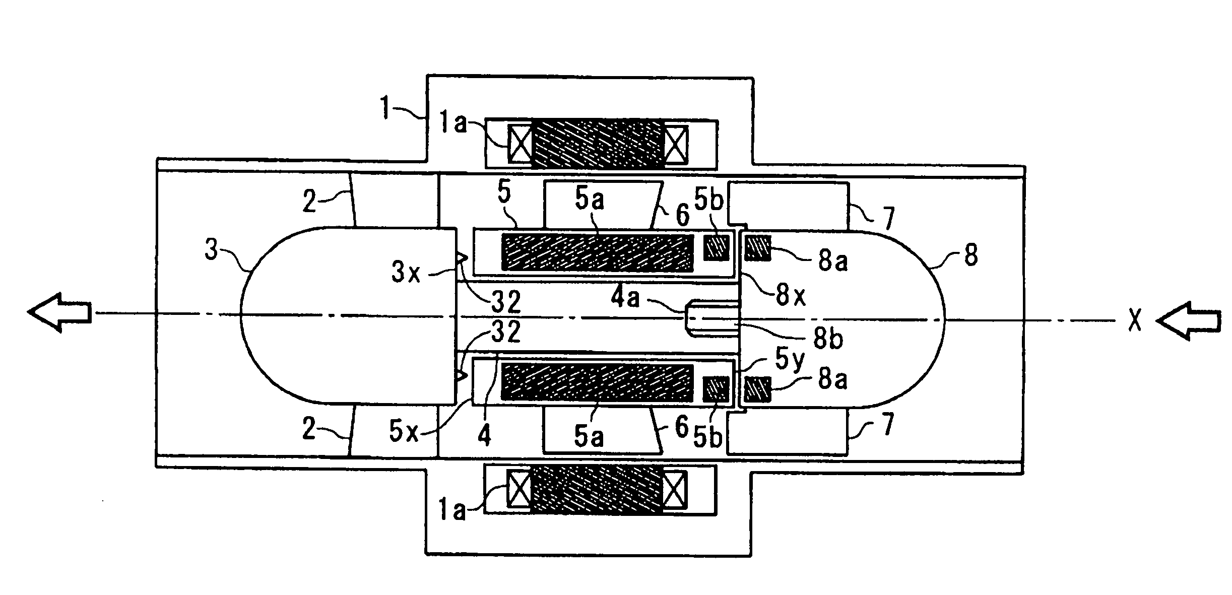
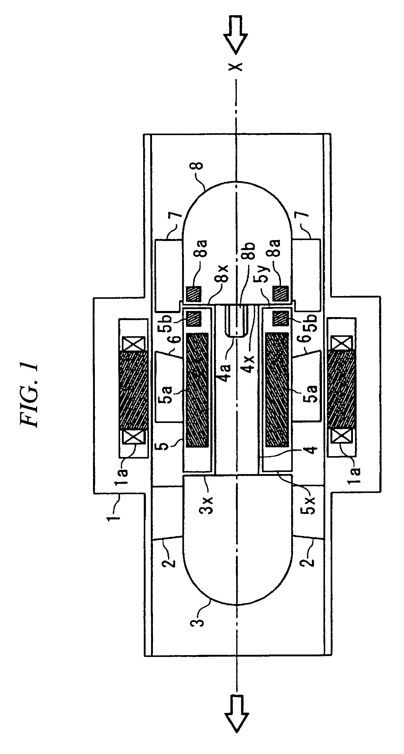
[0061]Referring now to the drawings, a first embodiment of the present invention will be described hereinafter. FIG. 1 is a cross-sectional view showing a configuration of an artificial heart pump in accordance with the present embodiment. Hereinafter, the words “before / front” and “after / rear” will be referred as the front side (upstream-side) and the rear side (downstream-side) respectively, in accordance with the flow of the blood. In addition, same as FIG. 26, an artificial heart pump in FIG. 1 will be described by taking an artificial heart pump, being provided with both hydrodynamic bearings and passive type of repulsive magnetic bearings, as an example.

[0062]An artificial heart pump in FIG. 1 comprises a cylindrical housing 1; a plurality of diffuser vanes 2 that are connected to an inside wall surface of the housing 1; a fixed body 3 that is supported by the housing 1 by having a plurality of diffuser vanes 2 stick out from an outside wall surface thereof a fixed shaft 4 that...

second embodiment

[0073]Referring to the drawings, a second embodiment of the present invention will be described hereinafter. FIG. 6 is a cross-sectional view showing a configuration of an artificial heart pump in accordance with the present embodiment. In FIG. 6, same portions as in FIG. 1 will be provided with same symbols, and the detailed description thereof will be omitted.

[0074]In addition to a configuration of the artificial heart pump in FIG. 1, an artificial heart pump in FIG. 6 has more than one adjustment ring 9, which adjusts a gap between the front end surface 5y of the sleeve 5 and the rear end surface 8x of the fixed body 8, installed between the rear end surface 8x of the fixed body 8 and the front end surface 4x of the fixed shaft 4. At this time, by having the adjustment rings 9 installed around each protruding portion 8b of the fixed body 8, respectively, and by inserting the fixed body 8, around which the adjustment rings 9 are installed, into the hole 4a of the fixed shaft 4, th...

third embodiment

[0076]Referring to the drawings, a third embodiment of the present invention will be described hereinafter. FIG. 7 is a cross-sectional view showing a configuration of an artificial heart pump in accordance with the present embodiment. In FIG. 7, same portions as in FIG. 1 will be provided with same symbols, and the detailed description thereof will be omitted.

[0077]In the artificial heart pump in FIG. 7, being different from the artificial heart pump in FIG. 1, the outer edges of the stationary vanes7 are connected to the inside wall surface of the housing 1 so a to have the fixed body 8 fixed, and the fixed shaft 4 is divided into two fixed shafts 41 and 42, which are connected to the fixed bodies 3 and 8, respectively. In this artificial heart pump, first of all, after the fixed body 3 being equipped with the diffuser vanes 2 is fixed inside the housing 1 by having the outer edges of the diffuser vanes 2 fastened to the inside wall surface of the housing 1, the sleeve 5 being equ...


PUM


Abstract

By inserting a protruding portion (8b), which is installed to a center position of a rear end surface (8x) of a fixed body (8), into a hole (4a), which is provided to a center position of an end surface (4x) on a side of a fixed body (8) of a fixed shaft (4) that is connected to a fixed body (3), the fixed bodies (3) and (8) and the fixed shaft (4) are connected. As a result, a sleeve (5) can be removed only by dismantling the fixed body (3).

Description

TECHNICAL FIELD[0001]The present invention relates to an artificial heart pump and especially relates to an artificial heart pump employing an axial-flow pump that pumps the blood.BACKGROUND ART[0002]Conventionally, an artificial heart pump which pumps the blood by utilizing the rotation of the impeller is employed as an alternate being used for medical purposes or as an assist pump being used for medical purposes. An artificial heart pump utilizing a roller pump or a centrifugal pump and an artificial heart pump utilizing an axial-flow pump are provided as the aforementioned artificial heart pump. Among these various types of artificial heart pumps, the artificial heart pump utilizing an axial-flow pump can reduce the size thereof, being compared with the artificial heart pump utilizing a roller pump or a centrifugal pump.[0003]The conventional artificial heart pump utilizing an axial-flow pump includes a housing that houses motor stators therein, and at the same time, includes a r...

Claims


Application Information

Patent Timeline
Patent Type & Authority Patents(United States)
IPC IPC(8): F04B35/04A61M1/10A61M37/00F01D3/00
CPCA61M1/101F04D13/06F04D29/048F04D29/44A61M1/1015A61M1/1017A61M1/1031A61M1/12A61M60/824A61M60/82A61M60/422A61M60/148A61M60/237A61M60/806
Inventor HIDAKA, TATSUYAOSADA, TOSHIYUKIOKUBO, TAKESHIKAKIUCHI, YOHEI
Owner MITSUBISHI HEAVY IND LTD
Why Eureka
Try Eureka