Sensor network system and data processing method for sensor network

a sensor network and data processing technology, applied in data switching networks, instruments, frequency-division multiplexes, etc., can solve problems such as system shutdown, communication failure, communication overload, etc., and achieve the effect of ensuring the reliability of the sensor network system

Inactive Publication Date: 2012-04-17
HITACHI LTD
View PDF16 Cites 173 Cited by
  • Summary
  • Abstract
  • Description
  • Claims
  • Application Information

AI Technical Summary

Benefits of technology

[0011]This invention has been made in view of the above-mentioned problems, and it is therefore an object of this invention to prevent an overload on a communication path in a sensor net system while transferring information from sensor nodes in real time as possible.
[0013]This invention ensures reliability of a sensor net system by transferring information from sensor nodes as close to real time as possible without discarding the information completely while preventing the transfer rate of relay nodes from increasing to a level that makes a sensor network unstable.
[0014]This invention also makes sure that information that is urgent and beneficial to users is transferred without being lost or delayed.

Problems solved by technology

A communication failure may occur in a sensor net system when a router apparatus such as a relay station or a base station on a communication path between a sensor node and a server computer is required to transfer data in an amount that is equal to or more than a given per-unit-time amount and when that is large enough to cause a processing overload or a communication overload in the router apparatus.
A failure in one router apparatus may propagate all over the sensor net system, causing the system to shut down.
However, the prior art examples have a problem in that, when other factors than a trouble in the sensor node causes the overload of the router apparatus on the communication path, a communication failure in the router apparatus cannot be prevented since no sensor node is out of order and accordingly the need to check the level of communications is not recognized.
If more sensor nodes than the number of attendees expected upon designing of the sensor net system access the wireless network that is under control of a router apparatus serving as the relay node, the amount of information to be relayed by the router apparatus exceeds a designed value and the router apparatus suffers a communication failure despite the fact that no sensor node is out of order.
If a fire actually breaks out in a place where this sensor node is installed, data transfer requests from the sensor node rapidly increase in number.

Method used


Image

  • Sensor network system and data processing method for sensor network
  • Sensor network system and data processing method for sensor network
  • Sensor network system and data processing method for sensor network

Examples


first embodiment

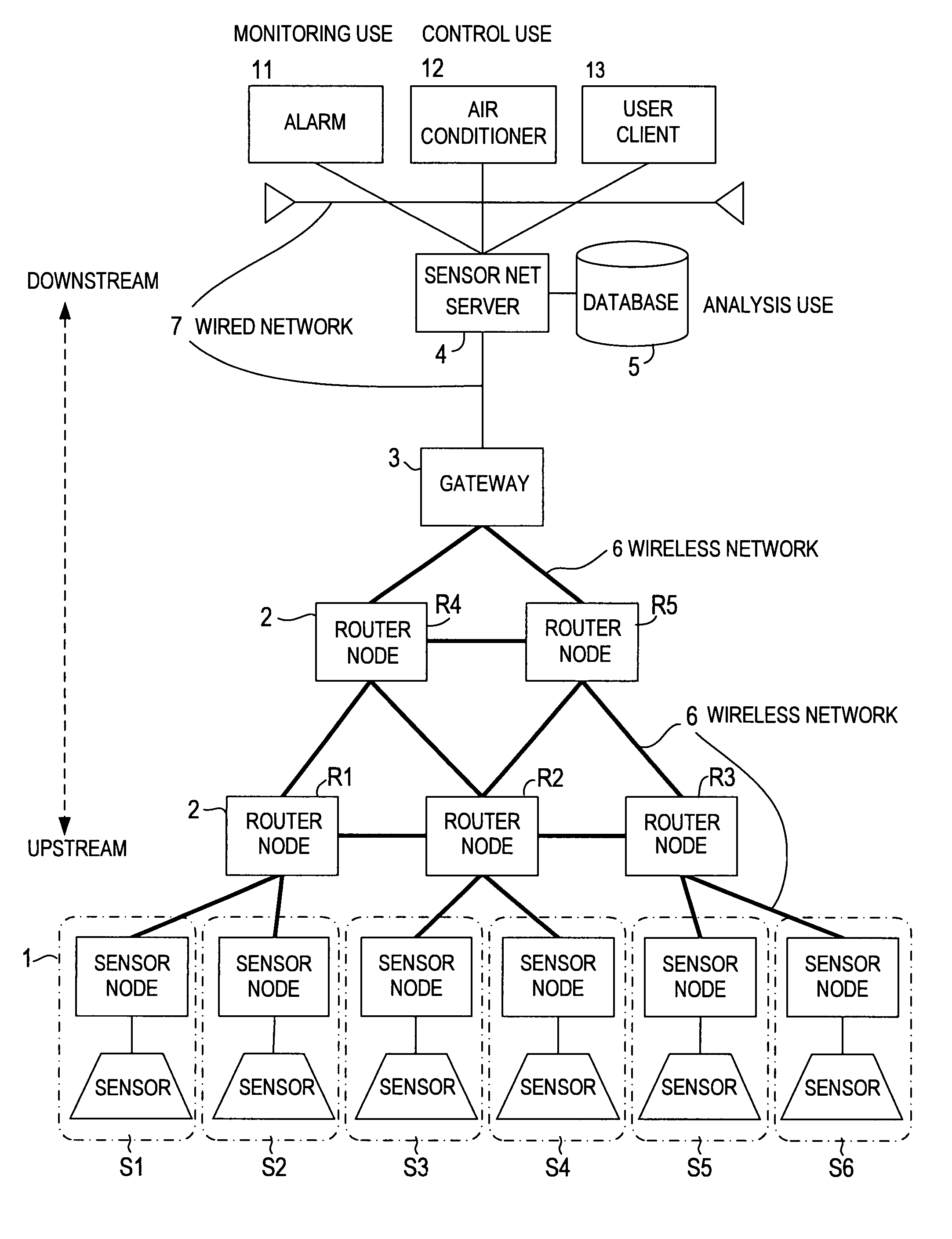
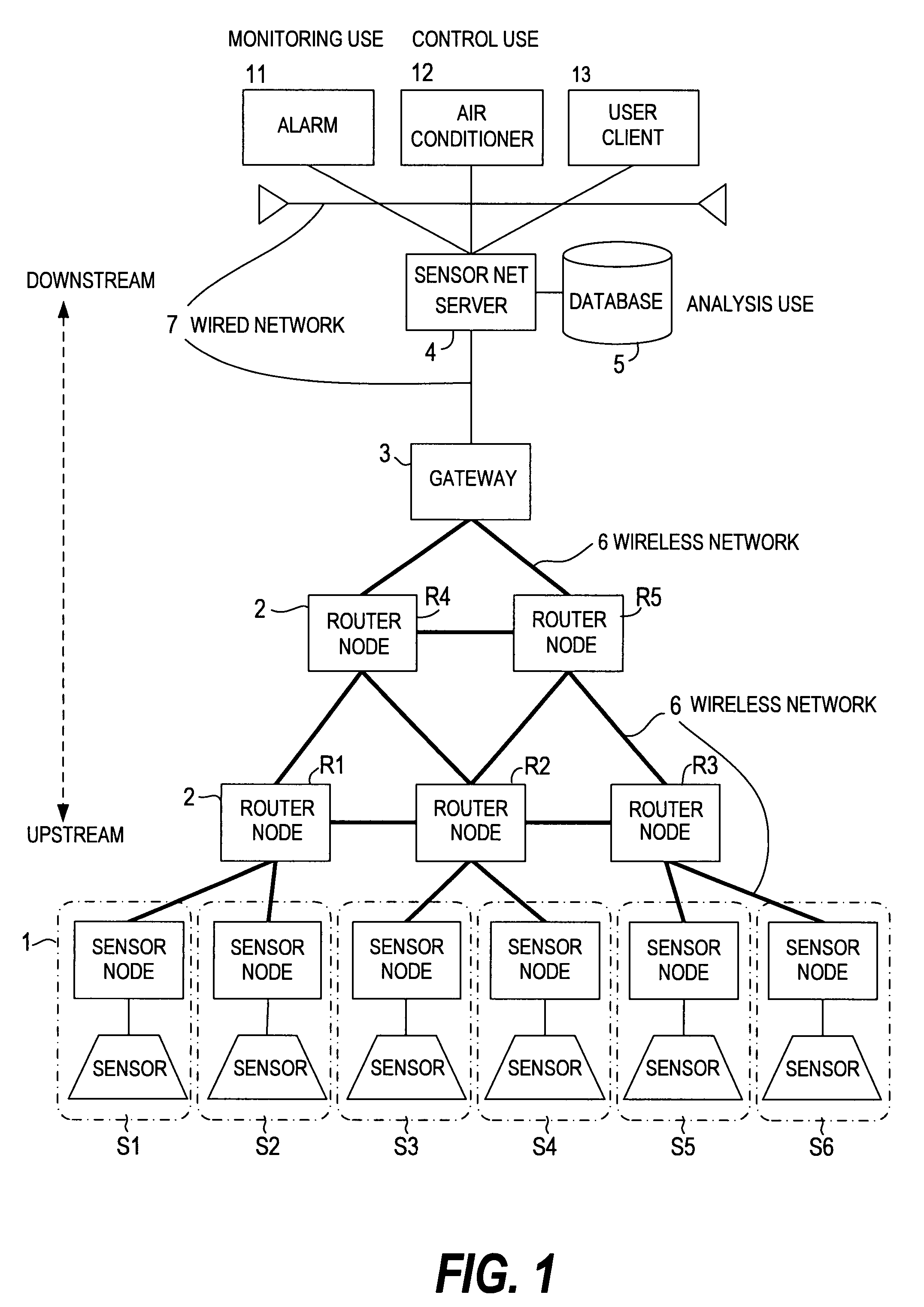
[0063]FIG. 1 is a block diagram showing an example of a sensor network system (hereinafter referred to as sensor net system) to which this invention is applied.

[0064]The sensor net system observes environmental information through sensors in many sensor nodes 1 dispersed throughout an environment. The observation information is delivered to a sensor net server 4 via router nodes 2 and a gateway 3 which are connected by a wireless network 6. The sensor net system thus collects observation information to the sensor net server 4 to serve as a computer system that assists a user in making a decision or the like. The sensor net server 4 has a database 5 which stores collected observation information.

[0065]Each sensor node 1 has a sensor such as a temperature sensor or a humidity sensor and an identifier for identifying an individual (person or subject), and is connected to one router node 2 via the wireless network 6. Each router node 2 has multiple sensor nodes 1 connected thereto, and ...

second embodiment

[0354]FIG. 39 shows a second embodiment of this invention. Unlike the first embodiment where a deceleration node and a deceleration processing executing node are determined after an excess transmission rate node is identified, the second embodiment omits identification of an excess transmission rate node in executing deceleration processing. The rest of the configuration of the second embodiment is the same as the first embodiment.

[0355]Shown in FIG. 39 is an example of deceleration processing of a sensor net system to which the second embodiment is applied. In FIG. 39, the sensor nodes S1 to S8, the router nodes R1 to R8, and the gateway GW are arranged in the same way as in FIG. 16 of the first embodiment.

[0356]In the example of FIG. 39, the sensor nodes S3, S5, and S6 are excess transmission rate nodes whose data transfer amount per unit time has increased to an excessive level. The router node R7 is a boundary node since the sum of the inflow velocity of the router nodes R5 and ...

third embodiment

[0390]FIGS. 46 and 47 show a sensor net system according to a third embodiment of this invention which has more than one gateway 3 and sensor net server 4 described in the first embodiment. The third embodiment shows an example in which the deceleration processing between router nodes described in the first embodiment is applied to event transfer between servers.

[0391]A personal area network (PAN) 60 constituted of the sensor node 1, the router node 2, and the wireless network 6 which are described in the first embodiment with reference to FIG. 1 is connected upstream to each gateway 3. Events from the sensor node 1 are transferred downstream to the gateway 3 by the PAN 60.

[0392]The sensor net server 4, which collects events transferred from the upstream, is connected downstream to each gateway 3 via the wired network 7.

[0393]A host server 41, which utilizes events collected by the sensor net server 4, is connected downstream to the sensor net server 4 via the wired network 7. The h...


PUM


Abstract

An overload on a communication path in a sensor network system is prevented while transferring information from a sensor node as close to real time as possible. When the transfer rate of events transferred from a boundary node (DR) toward a gateway (GW) exceeds a limit transfer rate (VL), one of nodes on the sensor node (S) side whose transmission rate meets a preset condition is identified as an excess transmission rate node. The excess transmission rate node, or a node that is not the excess transmission rate node and whose transmission rate should be reduced, is chosen as a deceleration node. A node that reduces the transmission rate of events from the deceleration node, or the transfer rate of the events, is chosen as a deceleration processing executing node. The deceleration processing executing node is instructed to execute preset processing.

Description

CLAIM OF PRIORITY[0001]The present application claims priority from Japanese application P2006-213338 filed on Aug. 4, 2006, the content of which is hereby incorporated by reference into this application.BACKGROUND OF THE INVENTION[0002]This invention relates to a technique of utilizing information from many sensor nodes that are connected to a network, and more particularly, to a sensor network system capable of smoothly delivering information sent from the sensor nodes.[0003]Sensor network system technology has been advancing in recent years. A sensor network system (hereinafter referred to as sensor net system) collects, via a network, sensing data which is obtained from many sensor nodes, and makes the information obtained from the many sensor nodes available over a network to computers and apparatuses that are located away from the sensor nodes.[0004]In a sensor net system, information obtained by many sensor nodes is sent to a server computer or the like via relay stations or ...

Claims


Application Information

Patent Timeline
Patent Type & Authority Patents(United States)
IPC IPC(8): H04L12/26G08C15/00H04L12/28H04L47/265H04W28/00H04W28/08H04W84/18
CPCH04W28/08H04L67/101H04L67/1012H04W84/18H04L67/1008H04L67/1002H04L67/1023H04L67/1001H04W28/10
Inventor MURO, KEIROOGUSHI, MINORUSUZUKI, KEI
Owner HITACHI LTD
Why Eureka
Try Eureka