
Signal processing device and method, and program

a technology of signal processing and processing device, applied in the direction of synchronisation signal speed/phase control, digital transmission, electrical apparatus, etc., can solve the problem of limiting the operable speed of the reception device for receiving the psk signal, the operating speed necessary for the block is subject to restraints, and the operating speed of the reception device is greater than the restraint due to the operating speed limit. , to achieve the effect of simple and more sure manner

Inactive Publication Date: 2012-04-24
SONY CORP
View PDF20 Cites 0 Cited by
  • Summary
  • Abstract
  • Description
  • Claims
  • Application Information

AI Technical Summary

Benefits of technology

This approach allows for simpler and more reliable detection of original data from PSK signals, overcoming speed limitations and enabling operation at higher carrier frequencies without the constraints of traditional digital circuit designs.

Problems solved by technology

Note however, upon detection being performed with the above-mentioned detection method using digital circuits, with regard to restriction as to the frequency of a PSK signal, restriction due to the operating speed limit of a reception device for receiving the PSK signal is greater compared with restriction due to the operating speed limit in a transmission device for transmitting the PSK signal.
Also, with the reception device, there is a possibility that the operating speed necessary for the block for processing data obtained with high-speed sampling at the sampling frequency several times the frequency of the carrier may exceed the operable limit thereof.
Therefore, the operable speed of the reception device is subjected to restraints due to the timing of settling of the sampling data, and more severe restraint conditions are imposed on the reception device as compared with the transmission device.

Method used


Image

  • Signal processing device and method, and program
  • Signal processing device and method, and program
  • Signal processing device and method, and program

Examples


Embodiment Construction

[0070]Before describing an embodiment of the present invention, the correspondence between the features of the claims and the specific elements disclosed in an embodiment of the present invention is discussed below. This description is intended to assure that an embodiment supporting the claimed invention is are described in this specification. Thus, even if an element in the following embodiment is not described as relating to a certain feature of the present invention, that does not necessarily mean that the element does not relate to that feature of the claims. Conversely, even if an element is described herein as relating to a certain feature of the claims, that does not necessarily mean that the element does not relate to the other features of the claims.

[0071]The present invention can be applied to a communication device, communication system, and so forth for processing digital signals such as ASK signals, PSK signals, Manchester code, or the like.

[0072]Description will be ma...


PUM


Abstract

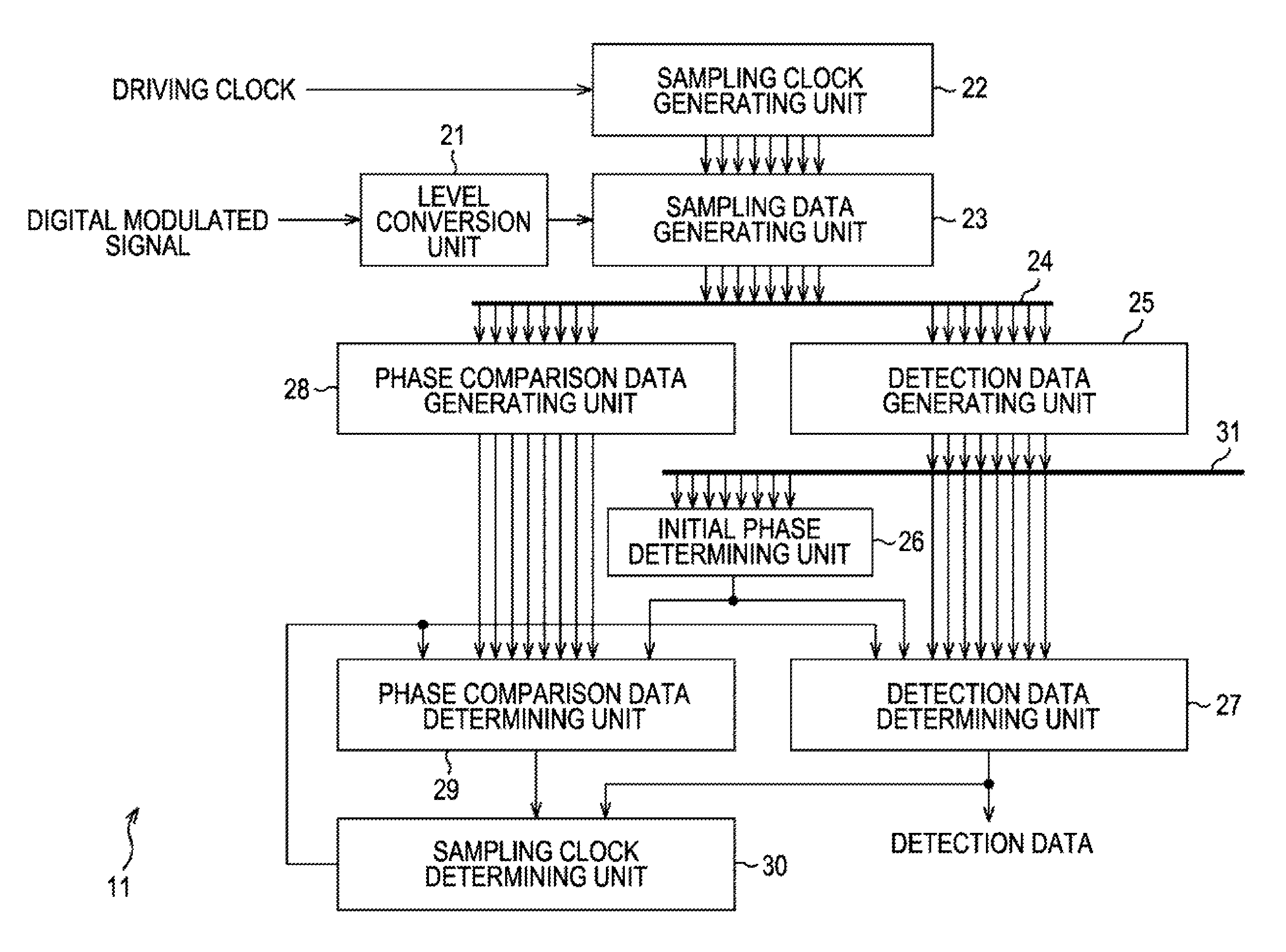
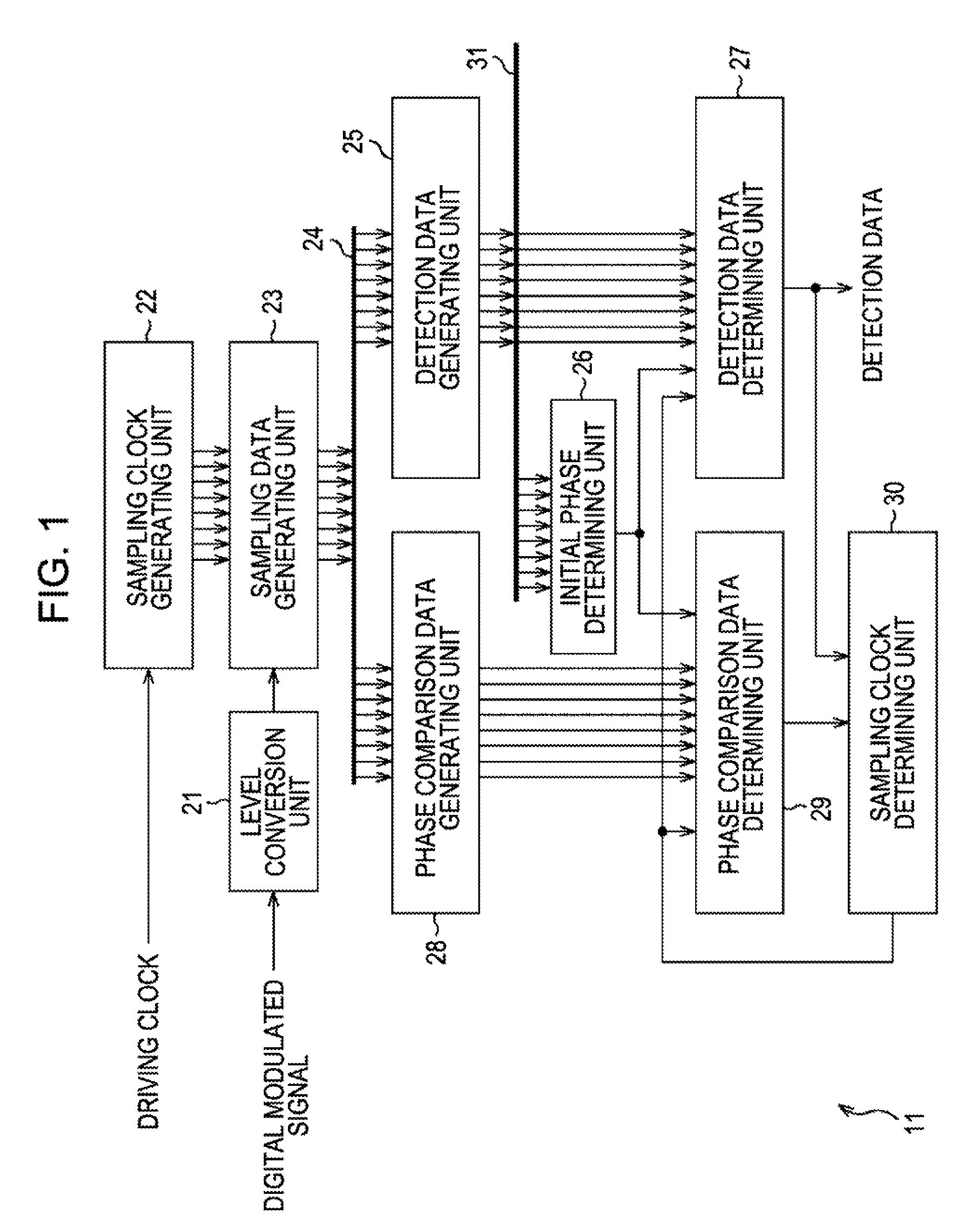
A signal processing device for detecting, from an input signal expressing data series, the data, including: a sampling clock generating unit for generating, from a driving clock with a predetermined cycle, multiple sampling clocks with mutually different phases and the same cycle as the cycle; a sampling data generating unit for sampling the input signal using the multiple sampling clocks, and generating a plurality of sampling data; a phase comparison data generating unit for generating phase comparison data indicating phase shifting as to the input signal of the sampling clock using the sampling data for each sampling clock; and a data generating unit for generating the data for each sampling clock using the sampling data, and selecting the data of the sampling clock having the phase closest to the phase of the input signal as the original data expressed with the input signal, based on the phase comparison data.

Description

CROSS REFERENCES TO RELATED APPLICATIONS[0001]The present invention contains subject matter related to Japanese Patent Application JP 2007-137874 filed in the Japanese Patent Office on May 24, 2007, the entire contents of which are incorporated herein by reference.BACKGROUND OF THE INVENTION[0002]1. Field of the Invention[0003]The present invention relates to a signal processing device and method, and a program, and particularly relates to a signal processing device and method, and a program whereby detection can be carried out simpler in a sure manner.[0004]2. Description of the Related Art[0005]With digital modulation methods for transporting a digital signal with a predetermined allocated band, a signal obtained by modulating the amplitude or phase of a predetermined carrier according to data is transmitted. Of these digital modulation methods, in particular, a method for modulating amplitude is called “amplitude modulation”, and a method for modulating a phase is called “phase m...

Claims


Application Information

Patent Timeline
Patent Type & Authority Patents(United States)
IPC IPC(8): H04L7/00H04L27/00
CPCH04L7/0337H04L7/10
Inventor IDE, NAOKI
Owner SONY CORP
Learn More