
Shackle apparatus

a technology of shackles and cables, applied in the direction of shackles, load-engaging elements, chain elements, etc., can solve the problems that the shackles on other slings or lifting cables defeat the purpose of the above-mentioned safety practices

Active Publication Date: 2012-05-08
USEFUL PRODS
View PDF40 Cites 23 Cited by
  • Summary
  • Abstract
  • Description
  • Claims
  • Application Information

AI Technical Summary

Benefits of technology

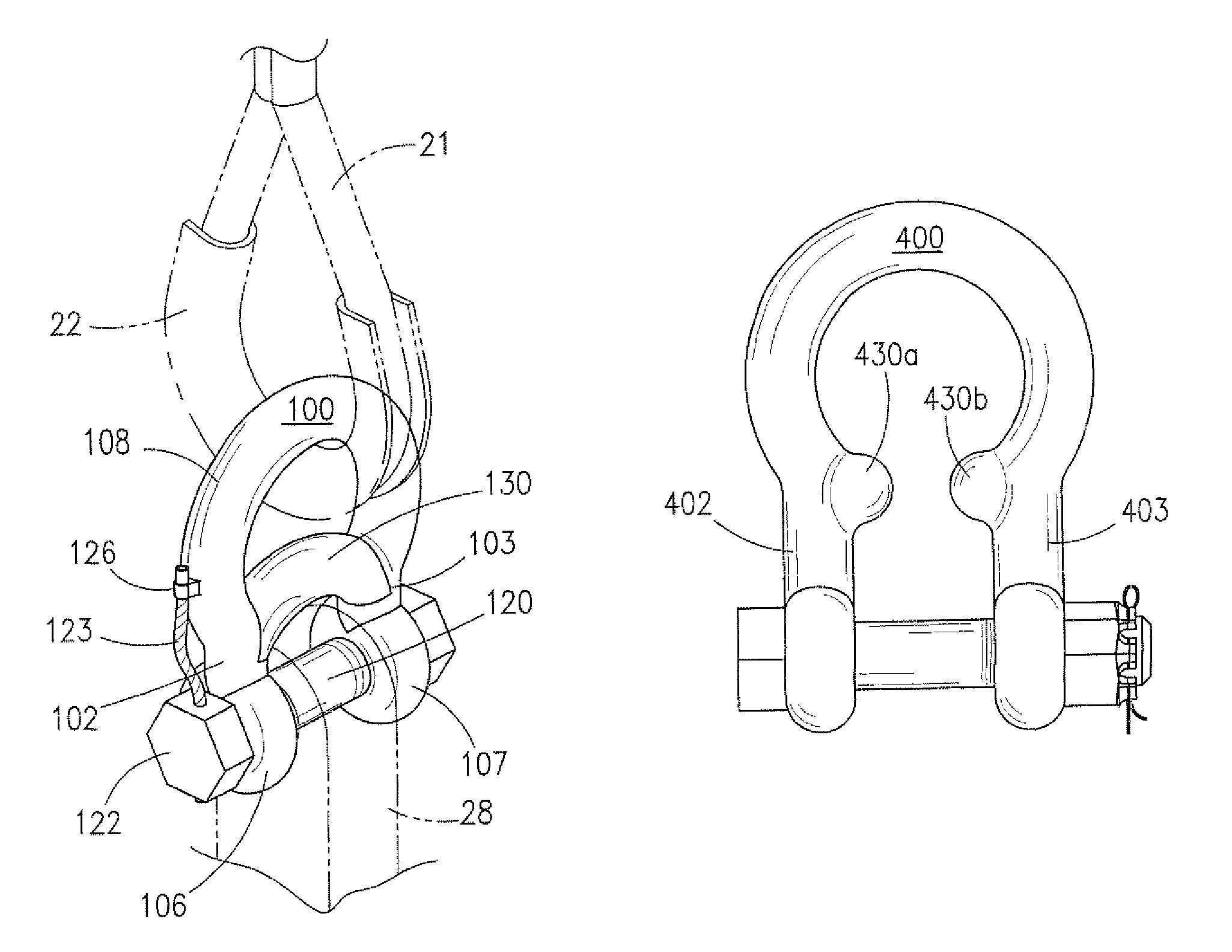
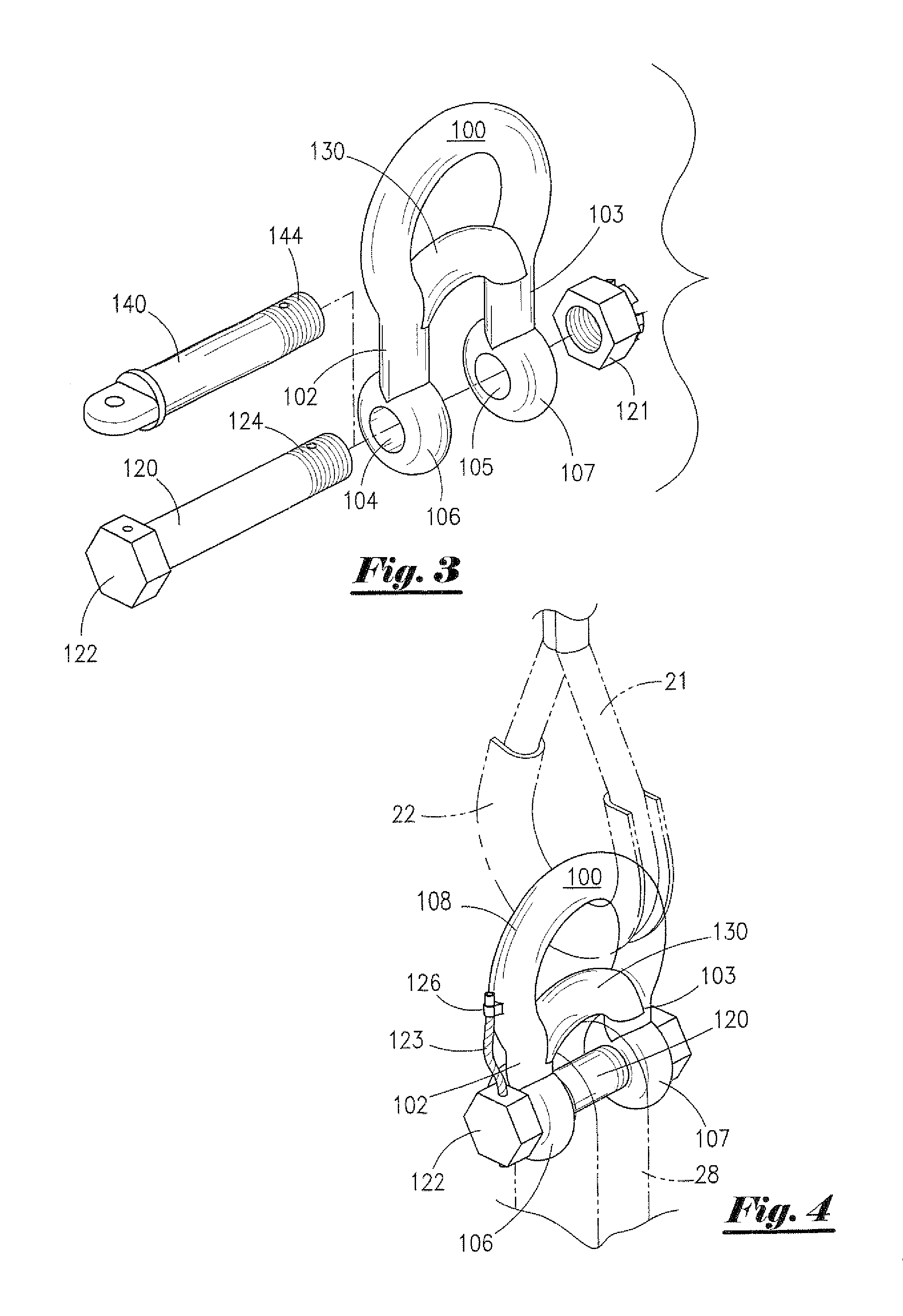
"The present invention is a shackle apparatus that is permanently attached to a lifting sling or cable. The shackle apparatus has a U-shaped body with an arcuate end and two parallel arms. A retaining member is between the arms and has transverse bores that align with the bores in the arms. The shackle apparatus can be attached to a load by inserting a bolt or other rigid member through the aligned bores and a complimentary hole in the load. The bolt or nut is secured in place using a threaded-nut or similar device. The shackle apparatus is designed to prevent unauthorized removal and installation on another sling or cable without causing damage or rendering it unusable. The shackle apparatus can be discarded after a predetermined threshold is met such as length of time or number of lifts. The shackle apparatus retains the bolt or nut within it, preventing unauthorized removal."

Problems solved by technology

The removal of shackles from such slings and re-use of such shackles on other slings or lifting cables defeats the purpose of the aforementioned safety practices.

Method used


Image

  • Shackle apparatus
  • Shackle apparatus
  • Shackle apparatus

Examples


Embodiment Construction

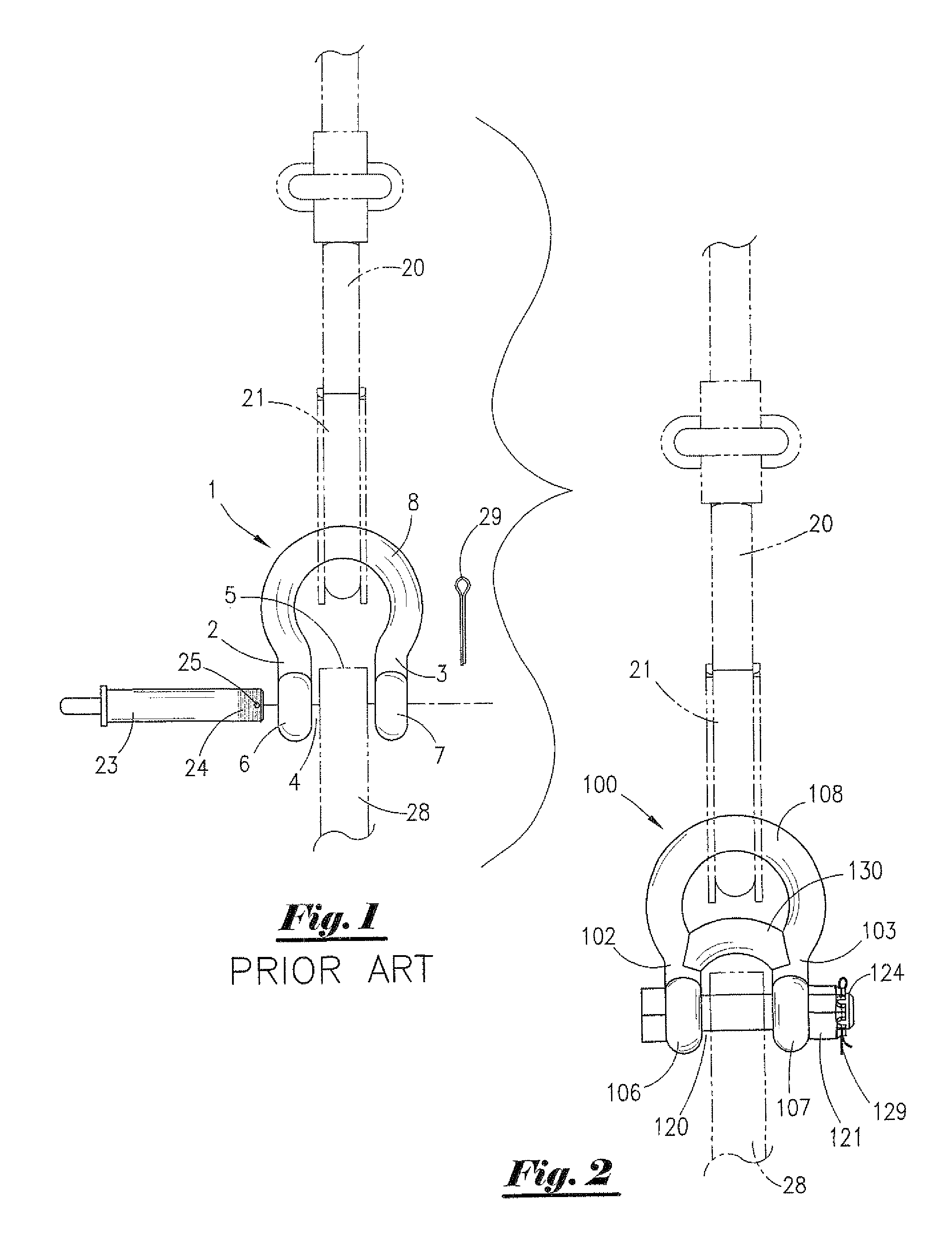
[0042]Referring now to the drawings, FIG. 1 depicts a partially-exploded front view of an embodiment of a conventional lifting assembly utilizing a prior art shackle member 1 having a curved, substantially U-shaped body section 8, first arm 2 and second arm 3. A throat or gap 5 is defined between said first arm 2 and second arm 3, and a mouth or opening 4 leads to said throat 5. Arms 2 and 3 of prior art shackle 1 also include substantially parallel ends 6 and 7 respectively. Substantially parallel ends 6 and 7 include aligned coaxial transverse bores 6a and 7a (not visible in FIG. 1), respectively, for receiving a bolt 23 or other rigid member.

[0043]In the conventional lifting assembly depicted in FIG. 1, mouth 4 of prior art shackle 1 is first passed through loop 21 of a sling or lifting cable 20. Coaxial transverse bores 6a and 7a of prior art shackle 1 are aligned with an opening (not visible in FIG. 1) in a lift lug or pad eye 28 of a load to be lifted. Bolt 23 is thereafter in...


PUM


Abstract

A shackle apparatus including a generally U-shaped shackle body having an arcuate end, a pair of parallel arms, and a retaining member spanning a gap defined between the shackle arms. The retaining member cooperates with the shackle body to define a closed loop which can be permanently attached to a sling or lifting cable. The retaining member prevents the shackle apparatus from being removed and installed on another sling or lifting cable without substantially destroying the shackle apparatus of the present invention.

Description

CROSS REFERENCES TO RELATED APPLICATION[0001]Priority of U.S. Non-Provisional application Ser. No. 12 / 952,445, filed Nov. 23, 2010, which is a Continuation of Non-Provisional application Ser. No. 12 / 802,901, filed Jun. 16, 2010, and Provisional Patent Application Ser. No. 61 / 296,958 filed Jan. 21, 2010, incorporated herein by reference, is hereby claimed.STATEMENTS AS TO THE RIGHTS TO THE INVENTION MADE UNDER FEDERALLY SPONSORED RESEARCH AND DEVELOPMENT[0002]NoneBACKGROUND[0003]1. Field[0004]The present invention relates generally to an assembly for connecting a sling, cable, or other lifting device to a load to be lifted. More particularly, the present invention relates to a shackle apparatus that is permanently attached to a set of slings, lifting cables or the like. More particularly still, the present invention relates to a captivated shackle apparatus that must also be discarded when attached slings or lifting cables are discarded. In an alternative embodiment, the shackle appa...

Claims


Application Information

Patent Timeline
Patent Type & Authority Patents(United States)
IPC IPC(8): F16G15/06B66C1/34
CPCB66C1/10F16G15/06B66C1/66B66C1/40
Inventor SEGURA, VICTOR J.
Owner USEFUL PRODS
Learn More