
Dynamic target tracking and positioning method of unmanned plane based on vision

A technology of dynamic target and positioning method, applied in the field of UAV navigation

Active Publication Date: 2013-06-12
BEIHANG UNIV
View PDF6 Cites 374 Cited by
  • Summary
  • Abstract
  • Description
  • Claims
  • Application Information

AI Technical Summary

Problems solved by technology

And the guidance of UAVs is angle guidance in most cases, not position guidance, so there are certain limitations

Method used


Image

  • Dynamic target tracking and positioning method of unmanned plane based on vision
  • Dynamic target tracking and positioning method of unmanned plane based on vision
  • Dynamic target tracking and positioning method of unmanned plane based on vision

Examples


Embodiment Construction

[0027] The present invention will be described in detail below in conjunction with the accompanying drawings and embodiments.

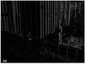
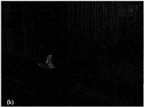
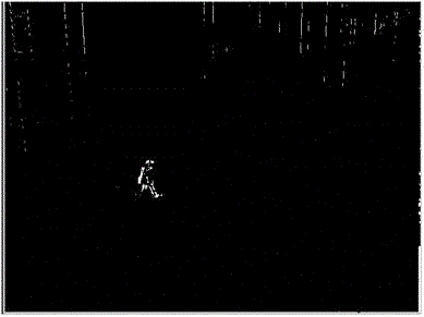
[0028] The present invention is a vision-based UAV dynamic target tracking and positioning method, which utilizes an airborne CCD camera to perceive the surrounding environment of the UAV flight area, uses an image processing algorithm to autonomously detect a moving target from the aerial video and displays it in the image. Stable real-time tracking, calculate the amount of miss, automatically adjust the rotation and pitch angle of the airborne gimbal to keep the tracked ground target near the optical axis of the camera, and measure the UAV and moving target in real time according to the monocular ranging model The distance between them determines the position coordinates of the moving target in the three-dimensional world, thereby guiding the UAV to track and fly.

[0029] To realize autonomous detection, tracking and positioning of moving targets, ...


PUM


Abstract

The invention discloses a dynamic target tracking and positioning method of an unmanned plane based on vision, and belongs to the navigation field of the unmanned planes. The dynamic target tracking and positioning method comprises the following steps of: carrying out video processing, dynamic target detecting and image tracking; carrying out cloud deck servo control; establishing a corresponding relationship between a target in the image and a target in the real environment, and further measuring the distance between a camera and a dynamic target to complete precise positioning of the dynamic target; and enabling an unmanned plane control system to fly by automatically tracking the dynamic target on the ground. The dynamic target tracking and positioning method of the unmanned plane based on the vision can automatically realize the movement target detecting, image tracking and optical axis automatic deflecting without the full participation of the people, so that the dynamic target is always displayed at the center of an image-forming plane; and the distance between the unmanned plane and the dynamic target is measured in real time according to an established model on the basis of obtaining the height information of the unmanned plane. Therefore, the positioning of the dynamic target is realized; closed-loop control is formed by using the positioned dynamic target as a feedback signal, so that the tracking flight of the unmanned plane is guided.

Description

technical field [0001] The invention belongs to the field of unmanned aerial vehicle navigation. It specifically relates to a vision-based UAV dynamic target tracking and positioning method. Background technique [0002] UAVs usually perceive the surrounding environment through visual sensors, and the ground station processes and analyzes the downlinked sensor information to obtain effective information to guide the UAV to fly. The optoelectronic equipment often carried by drones includes CCD photoelectric cameras, infrared thermal imaging cameras, and synthetic aperture radar imaging. Among them, the CCD camera can not only obtain high-resolution image intelligence, but also easily combine with the infrared focal plane array to form a multi-spectral imaging system, so it becomes the first choice or even the only photoelectric vision sensor for small UAVs. [0003] The UAV uses the onboard CCD camera to monitor the flight area. The acquired aerial image is compressed and t...

Claims


Application Information

Patent Timeline
Patent Type & Authority Applications(China)
IPC IPC(8): G05D1/12G06T7/20
Inventor 王宏伦苏斌嫔韩静雅
Owner BEIHANG UNIV
Learn More