Three-dimensional image display system

a display system and three-dimensional image technology, applied in the field of three-dimensional image display system, can solve the problems of enormous enhancement of display density of display devices at present, lack of real-time image generation of light beam reproduction techniques, and difficulty in visual observation of human beings approximately one minute in angular resolution

Inactive Publication Date: 2012-05-08
SONY CORP
View PDF5 Cites 2 Cited by
  • Summary
  • Abstract
  • Description
  • Claims
  • Application Information

AI Technical Summary

Benefits of technology

[0012]According to the light beam reproduction technique described above, since images are generated from light beams of an intensity with which they act effectively upon focal adjustment and binocular convergence angle adjustment as visual sensation functions, which have been almost impossible with two-eye and multi-eye type stereoscopic images, a stereoscopic image which provides very little fatigue to an observer can be provided. In addition, since light beams are continuously emitted in a plurality of directions from the same element on a virtual physical solid, the variation of the image upon movement of the viewpoint position can be provided continuously.
[0017]Therefore, it is desirable to provide a three-dimensional image display system wherein synchronous control when multi-parallax stereoscopic moving picture display is carried out can be carried out readily.
[0019]In the three-dimensional image display system, an image wherein control information is included in any of the parallax images is reproduced for every one frame or every plurality of frames. The three-dimensional image display apparatus carries out control in accordance with the control information included in the parallax images to carry out the multi-parallax stereoscopic moving picture display. Since the control information is included in the parallax images themselves, synchronous control where multi-parallax stereoscopic moving picture display is carried out can be carried out readily.
[0024]In summary, with the three-dimensional image display system, since control information is included in a parallax image itself and control is carried out in accordance with the control information included in the parallax image to carry out multi-parallax stereoscopic moving picture display. Therefore, synchronous control when multi-parallax stereoscopic moving picture display is carried out can be carried out readily.

Problems solved by technology

However, the image generated by the light beam reproduction technique at present lacks in provision of a sense of reality when compared with a physical solid in the real world.
Generally, it is considered that the limit to visual observation of a human being is approximately one minute in angular resolution, and a stereoscopic image by the light beam reproduction method at present is produced from an amount of light beams insufficient to the visual sensation.
However, tremendous enhancement of the display density of display devices at present is difficult from the problem of the light utilization efficiency or the diffraction limit.
In any case, in order to generate a high density light beam group, a plurality of devices are demanded, and increase in size of the entire apparatus may not be avoided.
However, if it is tried to reproduce high-definition moving pictures, then the art in the past has the following problem.
In particular, since the data amount of moving pictures is greater than that of still pictures, a large amount of data has to be transferred.
Besides, the large amount of data has to be transferred at a high speed.
According to the art in the past, since several seconds are demanded to transfer parallax images for generating a high definition stereoscopic still picture to individual reproduction apparatus, reproduction of moving pictures is difficult.

Method used


Image

  • Three-dimensional image display system
  • Three-dimensional image display system
  • Three-dimensional image display system

Examples


first embodiment

Modification to the First Embodiment

[0123]Now, a modification to the stereoscopic display apparatus according to the present embodiment is described.

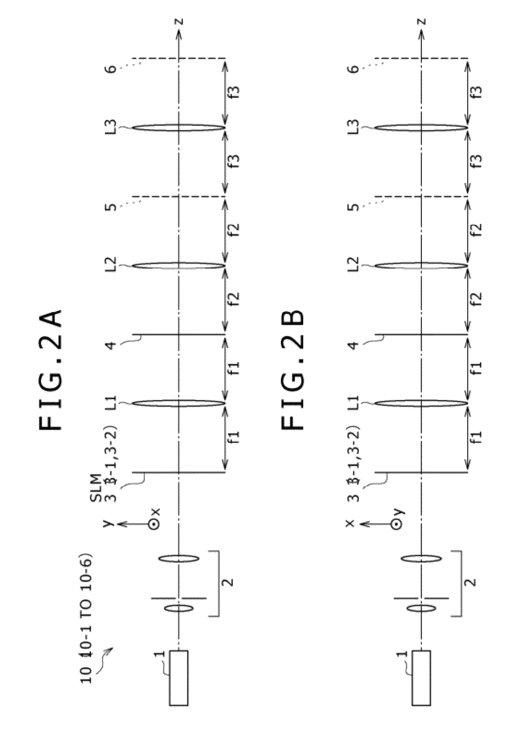
[0124]FIG. 22 shows the modification. While FIGS. 2A and 2B show the example of the configuration of the optical system wherein a spatial light modulator of the transmission type is used as the spatial light modulator 3, a spatial light modulator of the reflection type may be used instead. The spatial light modulator 3A of the reflection type may be, for example, a liquid crystal display apparatus of the reflection type or a display apparatus which uses a DMD (Digital Micromirror Device).

[0125]The three-dimensional image display system according to the first modification includes a beam splitter 7 on the optical axis. The beam splitter 7 has a function of passing or reflecting light depending upon the difference of a polarized light component. The beam splitter 7 reflects illumination light 70 toward the spatial light modulator 3A of th...

second embodiment

[0126]Now, a three-dimensional image display system according to a second embodiment of the present invention is described. While, in the first embodiment described above, the three-dimensional image display system has a configuration wherein a two-dimensional spatial light modulator is used for the spatial light modulator 3, the present embodiment is a three-dimensional image display system which uses a one-dimensional spatial light modulator which generates a one-dimensional image in place of the spatial light modulator 3.

[0127]FIG. 23 shows an example of a configuration of the three-dimensional display apparatus. Referring to FIG. 23, the three-dimensional display apparatus shown includes a grating light valve (GLV) device 41 serving as a one-dimensional spatial light modulator, a scanning object system for developing the one-dimensional image generated by the GLV device 41 in a two-dimensional space to generate a two-dimensional image, a grating filter 45 disposed on a generatio...

third embodiment

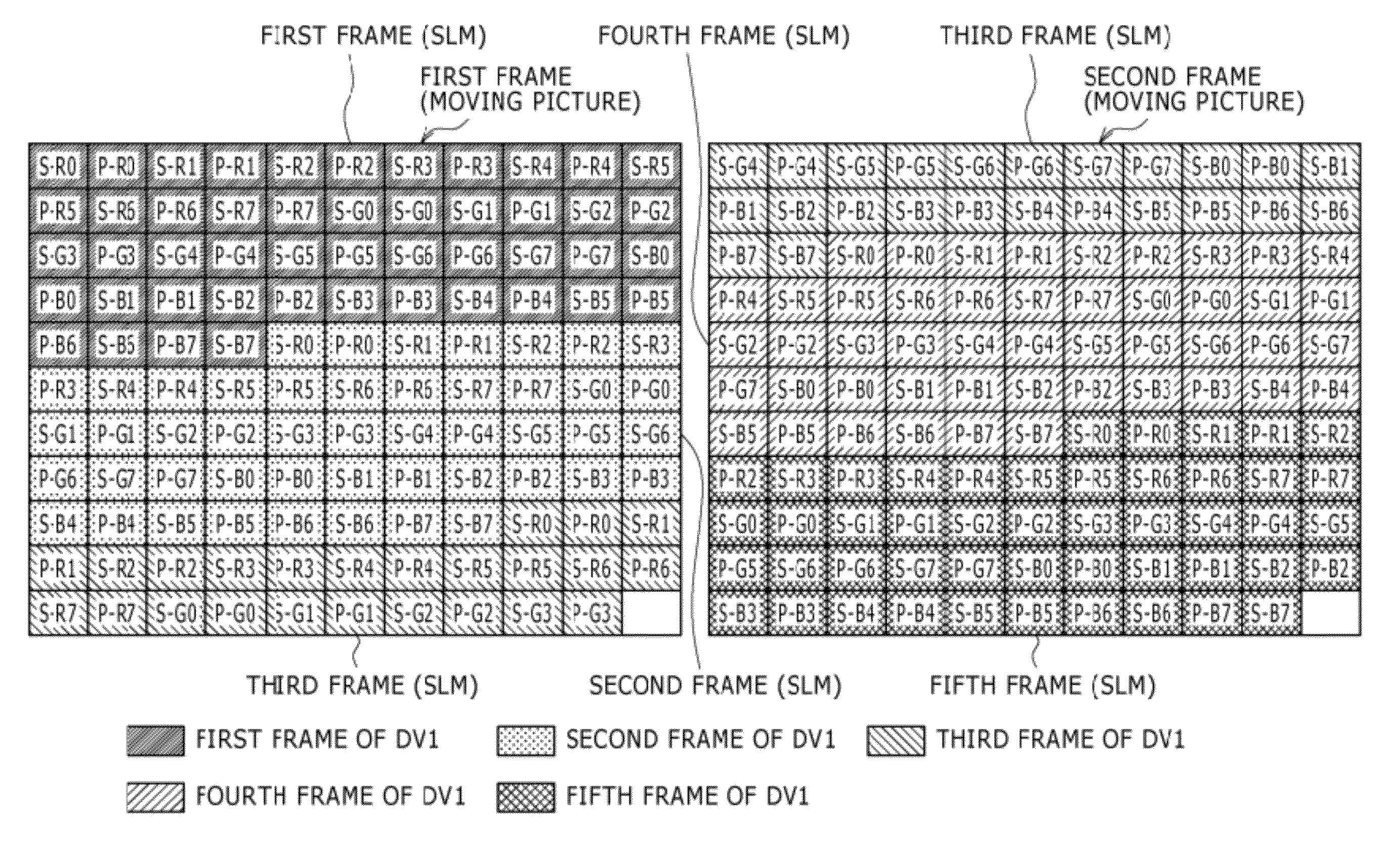
[0133]Now, a three-dimensional image display system according to a third embodiment of the present invention is described. While, in the first embodiment described hereinabove, the parallax images are binary images, the present invention can be applied also where the parallax images have gradations (gray scale) of two bits or more. In this instance, the image signal generation section 12 of each reproduction PC 15 should be configured such that it divides one frame into a plurality of bit plane groups and outputs an image signal wherein each of the bit plane groups is formed from two or more bit planes. Then, information of at least one parallax image should be applied to each bit plane group such that gradation representation is carried out within each bit plane group. The display periods of the bit plane groups are set equal to each other. It is to be noted that it can be considered that, in the first embodiment described hereinabove, one bit plane is allocated to one bit plane gr...


PUM


Abstract

Disclosed herein is a three-dimensional image display system, including: a multi-parallax image reproduction apparatus configured to reproduce two-dimensional images, which include a plurality of parallax images within one frame, at a first frame rate; and a three-dimensional display apparatus configured to carry out multi-parallax stereoscopic moving picture display at a second frame rate based on a plurality of parallax images reproduced by the multi-parallax image reproduction apparatus where one frame of stereoscopic moving pictures is formed from a multi-parallax image formed from a predetermined number of parallax images; the multi-parallax image reproduction apparatus reproducing an image wherein control information is included in any of the parallax images for every one frame or every plurality of frames, the three-dimensional image display apparatus carrying out control in accordance with the control information included in the parallax images to carry out the multi-parallax stereoscopic moving picture display.

Description

CROSS REFERENCES TO RELATED APPLICATIONS[0001]The present invention contains subject matter related to Japanese Patent Application JP 2007-026760 filed in the Japan Patent Office on Feb. 6, 2007, the entire contents of which being incorporated herein by reference.BACKGROUND OF THE INVENTION[0002]1. Field of the Invention[0003]This invention relates to a three-dimensional image display system for carrying out multi-parallax stereoscopic display based on a plurality of parallax images.[0004]2. Description of the Related Art[0005]In the past, as a technique for generating a stereoscopic image, a two-eye type stereoscopic image technique wherein images different from each other called parallax images are shown to both eyes of an observer so that the observer can feel a stereoscopic effect and a multi-eye type stereoscopic image technique wherein a plurality of sets of parallax images are prepared such that a stereoscopic image from different viewpoints is provided are available, and var...

Claims


Application Information

Patent Timeline
Patent Type & Authority Patents(United States)
IPC IPC(8): H04N13/04G02B27/22G03B35/16G03B35/18G09G3/20G09G3/34G09G3/36G09G5/00G09G5/18G09G5/36
CPCH04N13/0418H04N13/0497H04N13/32H04N13/398
Inventor SUZUKI, YOSHIOLU, QINGYUISWAMOTO, KYOHEIYU, XUEMING
Owner SONY CORP
Why Eureka
Try Eureka