
Absolute coordinate, single user-interface element pointing device

a pointing device and user interface technology, applied in the field of mouselike pointing devices, can solve the problems of inability to use, inability to use, and inability to use, and achieve the effect of maximizing the accuracy of cursor pointing and reducing user fatigu

Inactive Publication Date: 2009-05-26
WESTING SOFTWARE
View PDF9 Cites 0 Cited by
  • Summary
  • Abstract
  • Description
  • Claims
  • Application Information

AI Technical Summary

Benefits of technology

"The present invention provides an absolute coordinate pointer device with a single control element that can be used by handicapped users and emulated mouse clicks. The device includes a mechanism that moves a lightweight reflective material in the (x-y) plane using the single control element. The cursor movement data is sensed using an optical sensor system fixedly mounted within the device housing. The user can change the control element for different uses, such as using a pen-shaped element or a prosthesis-engageable element. The device can be used with a glide surface or a pantographic mechanism to prevent rotational movement of the reflective material. The cursor movement data and emulated mouse-click data can be communicated to the companion computer in conventional formats. The invention reduces stress and the likelihood of repetitive stress injury (RSI) by reducing the mass and repetitiveness associated with using the device."

Problems solved by technology

While such tasks may not be overly challenging for many users, these tasks can be overwhelming to handicapped users, as will now be described.
However such pointing devices are not absolute coordinate devices in the sense that the user cannot tell by looking at the device where on the computer display the cursor may be found.
However, manipulating an optical mouse requires essentially the same manual dexterity as manipulating a more conventional mouse, which dexterity is often not available to all would be users.
However as soon as the stylus is lifted from the digitizer tablet, the user can no longer look at the tablet and discern where on the computer display the cursor will be found.
But many users, especially physically handicapped users, find it difficult if not impossible to use prior art pointing mechanisms.
Grasping and moving mice, or grasping and moving trackball devices to manipulate a cursor and then having to move a finger to click buttons may literally be impossible if the user suffers from carpal tunnel syndrome, arthritis, or perhaps has a hand prosthesis.
Further, the inability to change how the user interacts with such devices promotes repetitive stress syndrome.
It is this sheer repetitiveness of user-interaction, coupled with the amount of user-generated force associated with using a conventional mouse or trackball device day-in and day-out that contributes to repetitive stress injury (RSI), even to an otherwise healthy user.
Even for non-handicapped users, the requirement of maintaining one hand on the device while pressing button(s) with a finger in a repetitive position, day-in, day-out, can result in physical disability, including tendonitis and carpal tunnel syndrome.
However such devices do not provide absolute coordinate information to the user, do not provide right-clicking, and can be difficult to maneuver, especially for the handicapped.
It turned out that double-clicking with the devices was difficult, especially for the handicapped.
In essence, while friction between the interface element and the underlying glide surface should be low for ease of user-controlled cursor movement, too low a coefficient of friction makes double-clicking difficult due to interface element movement between the two clicks.

Method used


Image

  • Absolute coordinate, single user-interface element pointing device
  • Absolute coordinate, single user-interface element pointing device
  • Absolute coordinate, single user-interface element pointing device

Examples


Embodiment Construction

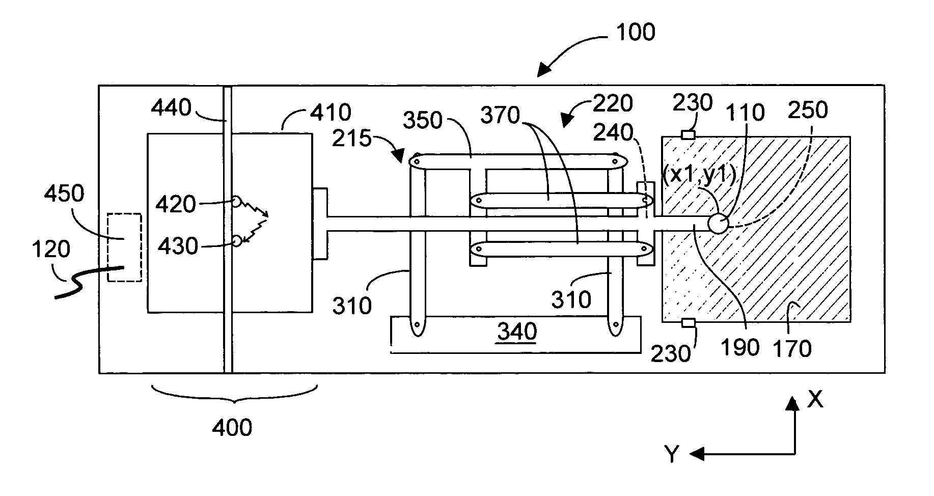
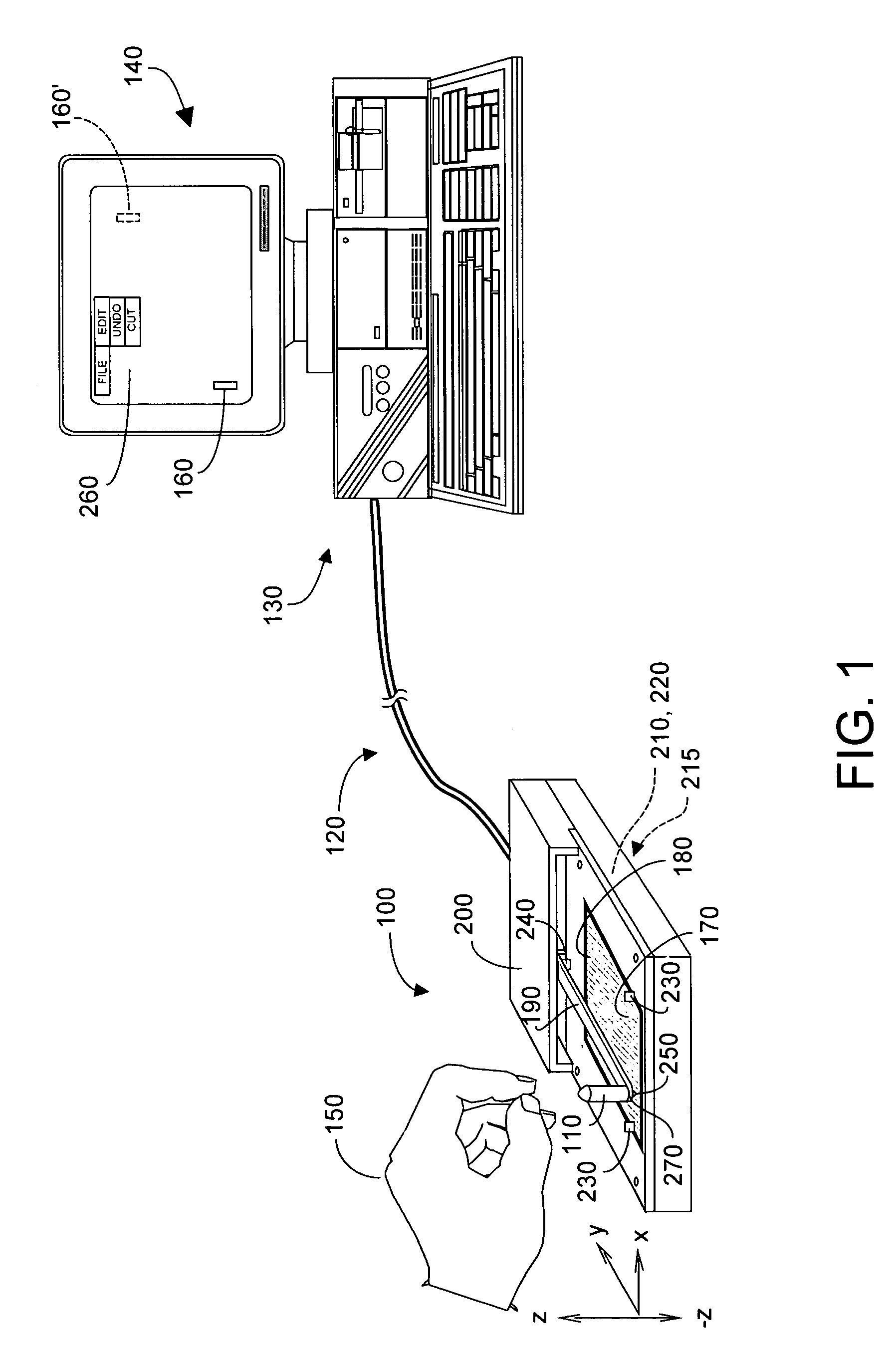
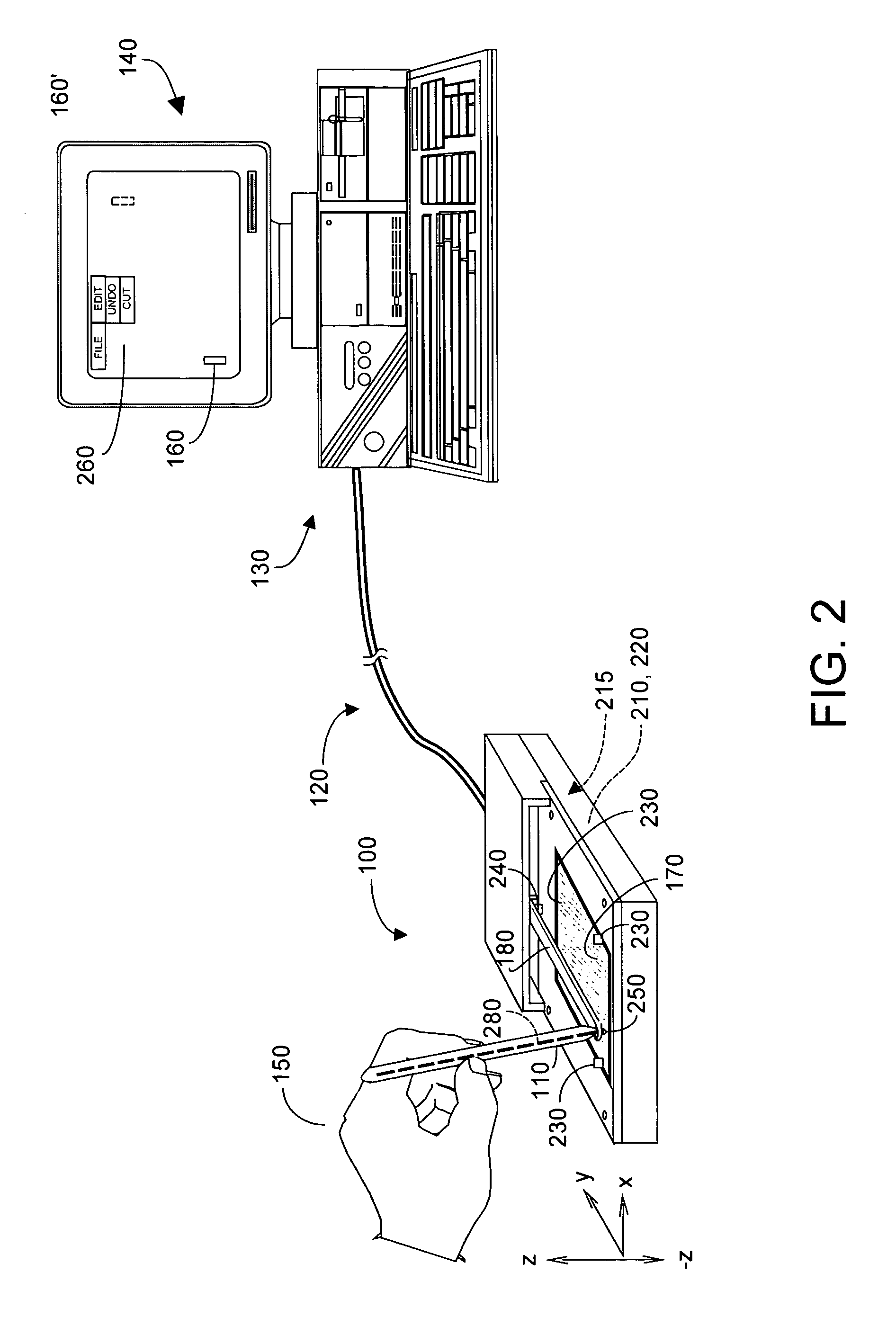
[0032]The description of the present invention commences with FIG. 6A. However it will be useful to first review the embodiments of applicant's parent application. FIG. 1 depicts an absolute coordinate pointer device 100 having a single control element 110 coupled via an interface 120 to a computer system 130 that includes a monitor or display 140. While interface 120 is depicted generically as a cable, it is to be understood that output signals from device 100 may instead be coupled to computer system 130 using infrared, radio signals, acoustic signals, among other communications media. Regardless of how the interface is implemented, output signals from device 100 will be received as input by computer system 130 in a format compatible with signals output from a generic off-the-shelf trackball and / or mouse input. It is further understood that while computer system 130 is shown as a PC-type computer, system 130 may in fact be a kiosk or other system to be controlled at least in part ...


PUM


Abstract

A pointing device includes a single control element to provide a user with absolute coordinate information and to enable user control of a computer cursor and emulation of mouse clicks. User movement of the single control element in an (x-y) plane preferably moves an optically reflective surface relative to an optical sensor system stationary within the device housing, such movement precluding rotation relative to the (x-y) plane. Mouse clicking may be emulated by moving the single control element up or down and / or by tilting relative to the (x-y) plane. Alternatively mouse clicking may be emulated by user activation of left and right sensor type switches or sensors. The device may be used by handicapped persons who can control cursor movement and mouse clicking using the single control element.

Description

PRIORITY TO CO-PENDING APPLICATIONS[0001]This is a continuation-in-part application from applicant's co-pending U.S. patent application Ser. No. 10 / 617,596 was filed Jul. 11, 2003 entitled “Absolute Coordinate, Single User-interface Element Pointing Device”, which application claimed priority from applicant's U.S. provisional patent application Ser. No. 60 / 452,835 filed on 7 Mar. 2003, entitled “Absolute Coordinate, Single User-interface Element Pointing Device”.FIELD OF THE INVENTION[0002]The invention relates generally to mouse-like pointing devices, and more particularly to pointing devices that reduce stress and repetition of user movements, and provide the user with absolute coordinate information and a single interface element useable to move a cursor, to left click, and to right click, and to fabricating such devices with a form factor small enough to fit within a standard computer keyboard, if desired.BACKGROUND OF THE INVENTION[0003]Pointing devices for use with computers a...

Claims


Application Information

Patent Timeline
Patent Type & Authority Patents(United States)
IPC IPC(8): G09G5/08A61F4/00G06F3/033G06F3/042
CPCA61F4/00G06F3/0334G06F3/03548G06F3/0421
Inventor OSBORN, JOHN J.
Owner WESTING SOFTWARE
Learn More