
Movement stabilizing apparatus for combination vehicle

a technology of moving stabilizer and combination vehicle, which is applied in the field of vehicles, can solve the problems of passenger car stability problems, tractor/trailer collisions, and vehicle collisions,

Active Publication Date: 2012-05-15
HONDA MOTOR CO LTD +1
View PDF16 Cites 62 Cited by
  • Summary
  • Abstract
  • Description
  • Claims
  • Application Information

AI Technical Summary

Benefits of technology

The invention is a movement stabilizing apparatus for a combination vehicle that can effectively suppress the pendulum movement of a trailer. It uses a yaw rate sensor, differential unit, cycle calculation unit, pendulum movement detection unit, and control amount output unit to detect and stabilize the movement of the trailer. The apparatus can output a control amount to a deceleration control device or yaw movement control device of the tractor to stabilize the traveling of the combination vehicle. The apparatus can also adjust the control amount based on the cycle or frequency of the pendulum movement to improve the stability of the vehicle. Overall, the invention provides a more accurate and efficient way to stabilize the movement of a combination vehicle.

Problems solved by technology

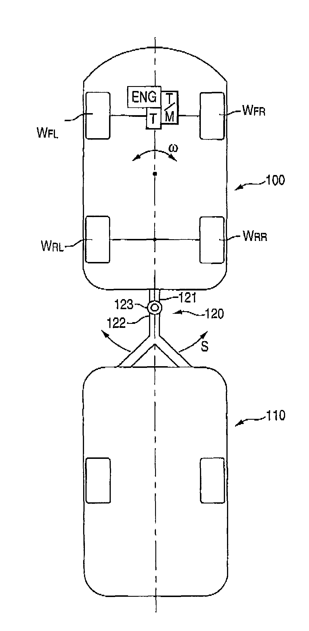
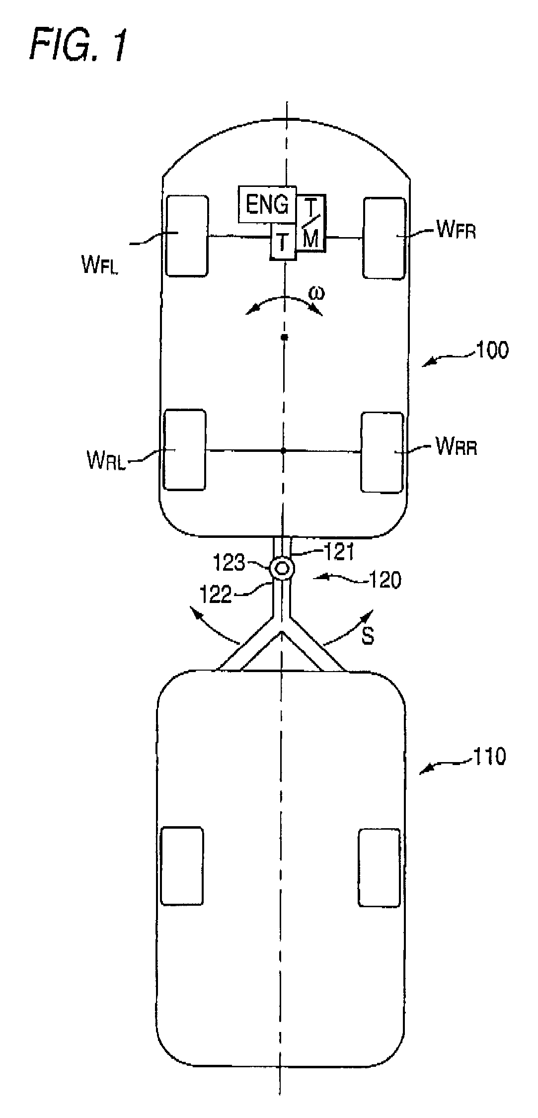
In automobiles (vehicles) towing trailers, a combination vehicle of tractor / trailer may begin to roll due to excessive speed, bad road conditions, crosswinds or the like.
Such a problem arises particularly in towing trailers which do not have their own actuators and sensors for stabilizing the traveling dynamics.
In particular, for trailers which have almost the same weights as passenger cars serving as tractors, the problem occurs.
Thus, stability problems occur in the passenger cars which are towing travel trailers, for example.
However, when the target yaw rate ωt is used for detecting the pendulum movement, by the reasons explained below, the suitable control value for damping the pendulum movement and the suitable output timing (phase) thereof can not be determined and hence there may arises an inconvenience for the control.
Thus, since the accurate cycle and amplitude of the pendulum movement can not be obtained, the suitable control value can not be calculated.
Thus, since it is impossible to generate a yaw moment which phase is completely in opposite to that of the deviation ωe, that is, the control is delayed in phase and the pendulum movement can not be damped sufficiently.

Method used


Image

  • Movement stabilizing apparatus for combination vehicle
  • Movement stabilizing apparatus for combination vehicle
  • Movement stabilizing apparatus for combination vehicle

Examples


modified example

[0164]Although the embodiment of the invention is explained in detail, the design of the invention can be changed in various manners without departing from the gist thereof.

[0165]In this embodiment, the control amount calculation portion 25f calculates the yaw control amount based on the yaw acceleration ωd′ outputted from the first-order lag processing portion 25d, and the control amount output portion 25g outputs the yaw control amount to the yaw moment control ECU 37 only when receiving the signal of the pendulum movement detection flag IFLAG=1 representing the determination of the detection of the pendulum movement from the pendulum movement detection portion 25e. Instead of such an arrangement, the invention may be arranged in a manner that only when the signal of the pendulum movement detection flag IFLAG=1 representing the determination of the detection of the pendulum movement is received from the pendulum movement detection portion 25e, the control amount calculation portio...


PUM


Abstract

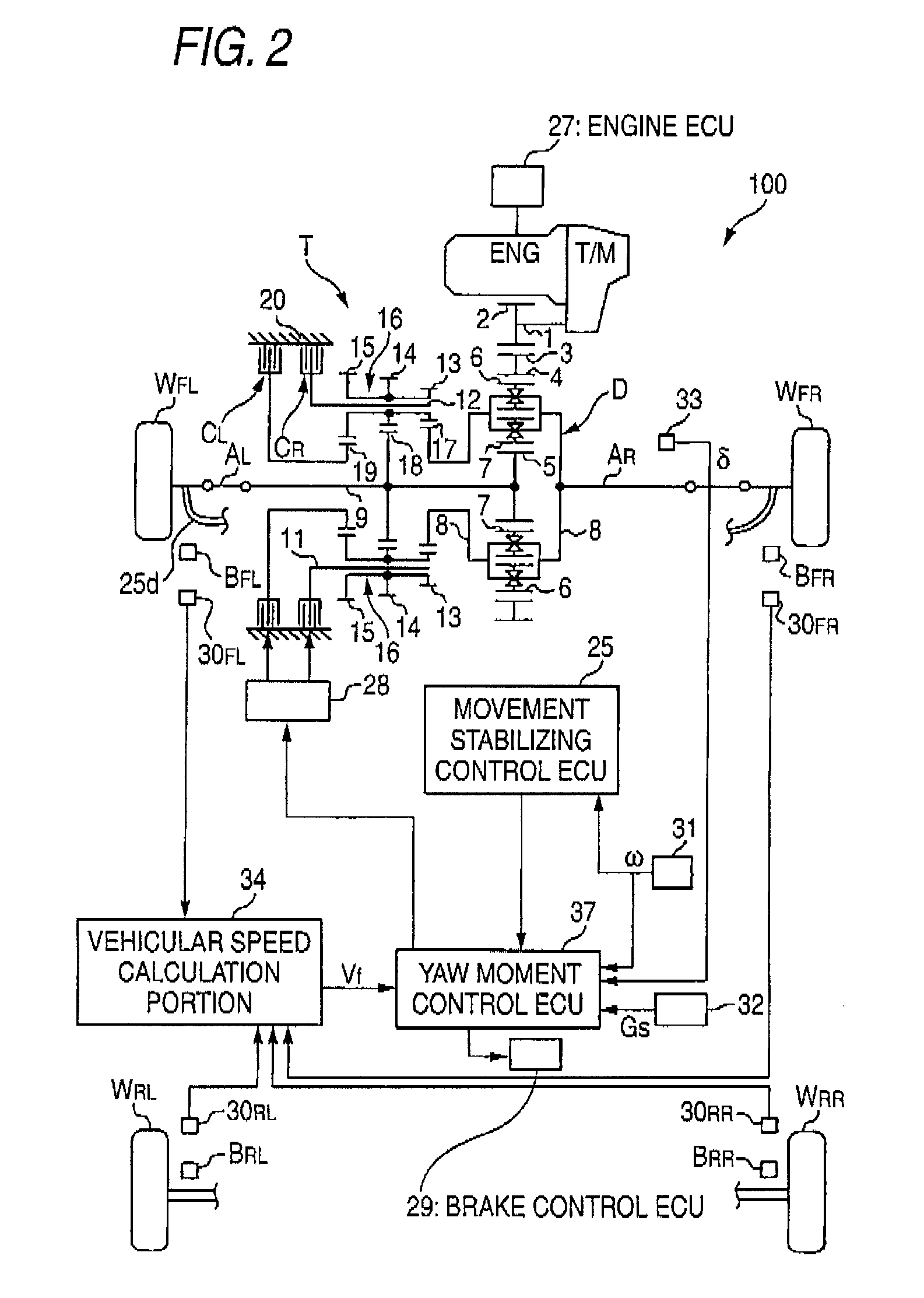
A movement stabilizing control ECU 25 includes a differential unit 25a, a cycle calculation unit 25b, a time constant / gain setting portion 25c, a first-order lag processing unit 25d, a pendulum movement detection unit 25e, a control amount calculation portion 25f and a control amount output unit 25g. The time constant / gain setting portion 25c sets a time constant τ and a gain K used at the time of subjecting a yaw acceleration ω′ which is a time-differential value of a yaw rate ω to the first-order lag processing at the first-order lag processing unit 25d, with reference to a function or data of a look-up table, for example, depending on the cycle or the frequency of the yaw acceleration ω′ due to the pendulum movement. The control amount calculation portion 25f multiplies the amplitude of a yaw acceleration ωd′ outputted from the first-order lag processing unit 25d by a predetermined constant to calculate a yaw control amount with a phase in opposite to that of the yaw acceleration ωd′ and outputs the yaw control amount to the control amount output unit 25g.

Description

BACKGROUND OF THE INVENTION[0001]1. Field of the Invention[0002]The present invention relates to a vehicle for towing a trailer and particularly relates to a movement stabilizing apparatus for a passenger car.[0003]2. Description of Related Art[0004]In automobiles (vehicles) towing trailers, a combination vehicle of tractor / trailer may begin to roll due to excessive speed, bad road conditions, crosswinds or the like. Such a problem arises particularly in towing trailers which do not have their own actuators and sensors for stabilizing the traveling dynamics. In particular, for trailers which have almost the same weights as passenger cars serving as tractors, the problem occurs. Thus, stability problems occur in the passenger cars which are towing travel trailers, for example.[0005]If a snake movement or a pendulum movement occurs in a combination vehicle composed of an automobile (vehicle) and a trailer, the trailer oscillates about its vertical axis and also oscillates the passenge...

Claims


Application Information

Patent Timeline
Patent Type & Authority Patents(United States)
IPC IPC(8): G06F7/70B60T7/20B60T8/1755B60W10/18B60W10/188B60W30/00B60W30/02B60W30/045
CPCB60T8/1708B60T8/1755B60T2230/06B60T2250/06
Inventor FUTAMURA, TOMOYUKIKOJIMA, TAKESHIMIYATA, KAZUAKI
Owner HONDA MOTOR CO LTD
Learn More